background image

34

WASHING MACHINE Series GWH / GWM / GWN

GENERAL DESCRIPTION

GWM / GWN DIMENSIONS

D

E

F

G

C

A

B

I J K

L

M

N

O

P

Q

R

S

T

V

U

Summary of Contents for GWH Series

Page 1: ...NS FOR USE AND MAINTENANCE OF THE 8 28 KG WASHING MACHINE WASHING MACHINE series GWM GWN GWH Edition 01 2015 via Masiere 211 c 32037 Sospirolo BL Italy Tel 39 0 437 848 711 Fax 39 0 437 879 108 e mail info grandimpianti com web www grandimpianti com ...

Page 2: ... by the user GENERAL CONSIDERATIONS Comply with all operating maintenance instructions and recommendations described in this manual For better results The Manufacturer recommends performing cleaning and maintenance operations regularly to keep the machine in the best conditions It is essential to train the personnel in charge of running performing maintenance and inspecting the machine in complian...

Page 3: ...3 RELEVANT DIRECTIVES 14 DEFINING THE OPERATOR QUALIFICATIONS 15 SAFETY GENERAL WARNINGS 15 OBLIGATIONS 20 PROHIBITIONS 20 RESIDUAL RISKS 21 SYMBOLS APPLIED TO THE APPLIANCE 23 INTENDED USE 26 IMPROPER REASONABLY PREDICTABLE USE 26 NOISE 27 VIBRATIONS 27 GENERAL DESCRIPTION 28 MAIN COMPONENTS 29 TECHNICAL DATA 30 GWH DIMENSIONS 32 GWM GWN DIMENSIONS 34 SAFETY DEVICES 36 SAFETY WARNINGS FOR TRANSPO...

Page 4: ... 53 LIQUID DETERGENT INTRODUCTION PUMP CONNECTION OPTIONAL 59 ELECTRICAL CONNECTION OF THE LIQUID DETERGENT AUTOMATIC DISPENSING SYSTEM 60 TESTING 61 SAFETY INSTRUCTIONS FOR MAINTENANCE 62 ROUTINE MAINTENANCE 63 VERIFICATION TABLE 63 TIGHTENING MOMENTS 63 OPERATIONS TO BE PERFORMED EVERY 1000 CYCLES 64 TRANSMISSION BELT TENSIONING 64 CLEANING 65 EXTRAORDINARY MAINTENANCE 68 REPLACING THE DOOR GASK...

Page 5: ...WASHING MACHINE Model GWH GWM GWN Year of manufacture 2015 Serial number MANUFACTURER IDENTIFICATION Name GRANDIMPIANTI ILE ALI S p A Address via Masiere 211 c 32037 Sospirolo BL Italy Tel 39 0 437 848 711 Fax 39 0 437 879 108 e mail info grandimpianti com web www grandimpianti com ...

Page 6: ...6 WASHING MACHINE Series GWH GWM GWN IDENTIFICATION SUPPLIER IDENTIFICATION Supplier importer Importer stamp DISTRIBUTOR IDENTIFICATION Distributor Distributor stamp ...

Page 7: ...8 24 28 Key Column 1 Manufacturer G Grandimpianti T Technolaundry Column 2 Type of machine W Washing machine D Dryer I Ironer B Barrier Column 3 Spinning capacity only for washing machines H High spin Factor G400 M Medium spin factor G 200 N Normal spin factor G 100 Column 4 Machine size in kg Column 5 Control NOTHING Guido control Z G4 Wiz control Column 6 Heating source E Electrical heating G Ga...

Page 8: ... transport document or invoice APPROVAL WRAS ETL UL CSA CE E T A D D O R P L E D O M SERIAL NR T H G I E W Y T I C A P A C E S U F w K R E W O P C I R T C E L E E G A T L O V D E T A R CE0694 15 E P Y T E C N A I L P P A N I P NATIONALITY ADJUSTED FOR GAS PRESSURE CATEGORY NOMINAL HEAT INPUT Qn Hi MADE IN IP CODE IP24D A B C D E F G S U H N L P M R Q O I T Pos Element A Company name B Approval C M...

Page 9: ...9 IDENTIFICATION DECLARATION OF CONFORMITY copy ...

Page 10: ...icating all data regarding the model serial number and defect of the appliance on which the component was assembled The warranty does not apply to appliances damaged due to negligence incorrect connections unsuitable installation failure to comply with assembly or user instructions and in any case altered by unauthorised personnel Moreover the warranty does not apply if the serial number has been ...

Page 11: ...sal even in case of transfer sale hire rent etc The attached manuals are an integral part of this documentation and the same recommendations prescriptions as those contained in this manual apply IMPORTANT Read these instructions for use and maintenance before proceeding with the installation and use of the appliance The instructions are also available on the website of the Manufacturer UPDATES If ...

Page 12: ...s manual Symbol Description Refer to the manual instruction booklet Mandatory action general signal General warning signal Explosion hazard warning signal Electrical hazard warning signal Hot surface hazard warning signal Fire hazard warning signal Poisoning and intoxication hazard warning signal Biological hazard warning signal ...

Page 13: ...ferent from a guard which reduces risk mechanical or electric devices WASHING Main phase of the washing cycle required to remove dirt from fabric DANGER Potential source of damage WEIGHING Phase of the washing programme used to detect the weight Kg of the load inside the drum PRE WASHING Phase of the washing cycle that helps loosen and remove organic dirt GUARD Part of an appliance used to provide...

Page 14: ...ANT DIRECTIVES For the appliance design construction and installation the following directives and standards have been referred to 2006 42 CE MACHINE DIRECTIVE 2004 108 EC ELECTRO MAGNETIC COMPATIBILITY DIRECTIVE 2006 95 EC LOW VOLTAGE DIRECTIVE GENERAL INFORMATION ...

Page 15: ...ble to perform routine maintenance and clean the appliance WARNING Operators must always adhere to The limits of their duties The warnings on the appliance safety plates The service procedures provided for SAFETY GENERAL WARNINGS IMPORTANT Read these instructions for use and maintenance before proceeding with the installation use and maintenance of the appliance IMPORTANT Keep this identification ...

Page 16: ...r s qualified employees and or authorised personnel following the instructions given in this instruction manual in accordance with local regulations WARNING The existing rules for connection to the local electricity network TT TN IT must be complied with It may not always be possible to connect systems in the standard version to the IT electricity networks Contact the Manufacturer WARNING All type...

Page 17: ...Make sure that in the place of installation of the appliance there is no possibility that the latter is exposed to direct or indirect water jets WARNING The appliance has not been designed for operation in in explosive atmospheres and or with such products WARNING Do not expose the appliance to the elements excessively high or low temperatures and humidity WARNING Mark the danger zone in the laund...

Page 18: ...elements low or high temperature and humidity levels Do not wet the washing machine WARNING Regularly check the operation of the door locking mechanism WARNING Disconnect the power supply turn off the water and steam supply before performing cleaning and maintenance as well as at the end of each working day WARNING Steam or hot air can leak from the vent on the rear of the appliance Do not obstruc...

Page 19: ...ectric shock and injury the appliance must be properly earthed WARNING Even if the main switch of the appliance is set to OFF the power supply clamps of the switch are always live WARNING Wait at least 10 minutes before performing maintenance on the device after disconnection from power Before performing maintenance on the inverter check that the residual voltage thereof is less than 30Vdc WARNING...

Page 20: ...not touch the washing machine with wet or damp hands or feet Do not use the washing machine barefoot Do not leave the appliance exposed to weather agents rain sea salt etc Do not smoke close to the washing machine during use Do not touch the water or steam loading pipes even when the appliance is not running Do not wash garments that carry the hand wash only or relative symbol care label Do not us...

Page 21: ...ture RISK OF SHEARING AND BURNING Do not place hands or objects in the tube connecting the tank to the dispenser or in the inverter ventilation protection device Risk of shearing and burning RISK OF SHEARING CRUSHING Do not insert hands or objects between the fixed part and the floating part of the appliance Risk of shearing RISK OF BURNING Do not touch the appliance porthole glass as it may reach...

Page 22: ...ey may reach high temperatures The steam intake pipes must be suitably insulated and protected B A C RISK OF FIRE Do not run a spin cycle with dry laundry RISK OF FIRE Do not use the appliance to treat fibres soaked or contaminated with flammable substances such as oil grease or fuels BIOHAZARD If the appliance is not used for a few days bacteria or micro organisms harmful for your health may sett...

Page 23: ...if these are not used for a long time Open the taps and let the water run for a few minutes before using the appliance RISK OF INHALING HARMFUL SUBSTANCES Risk of inhaling harmful substances upon opening the appliance dispenser door or near the air break device Pay attention Risk of inhaling of harmful substances SYMBOLS APPLIED TO THE APPLIANCE All the symbols that can be applied to the appliance...

Page 24: ...gerous voltage hazard Capacity of the fuses on the appliance Enabling the programming of no tokens in the appliances required for self service operation Steam supply input Condensation leakage from steam powered appliances Do not force the appliance opening with rotating drum or water in the tank Water steam hazard Clamp voltage Porthole closing opening movement Danger due to hot steam and inhalat...

Page 25: ... and prohibition to operate with moving parts USB port Attention electric hazard Disconnect the appliance from the mains before any intervention Do not tread Crushing hazard Advice for the installation and the wire section of the power supply wires Power supply disconnector device on the machine ...

Page 26: ...rried out promptly in case of necessity safety devices are not removed and or bypassed WARNING It is strictly forbidden to wash items of clothing soaked with flammable substances solvents acids and or grease WARNING Any other use that is not explicitly indicated must be considered dangerous WARNING Remove all traces of stony and or sandy material from fabrics before placing them into the washing m...

Page 27: ...here inside the machine NOISE During operating cycles the noise to which the personnel involved is exposed does not exceed 70 dB The actual noise level of the appliance installed at a site during operation in a production process is different from that detected since noise is influenced by some factors such as Type and characteristics of the site Duration of exposure Other adjacent appliances in o...

Page 28: ... to safeguard for the operator s safety The appliance can be automated by installing an external liquid soap dispenser and a pump conveying liquid soap inside the appliance the pump is an optional item The appliance work cycle standard without optional elements can be divided as follows Phase Description 1 Introduction of the laundry to be washed into the steel drum 2 Introduction into the soap di...

Page 29: ... of Pos Element 1 Detergent dispenser 2 Control panel 3 Side panels 4 Laundry loading unloading porthole 5 Mixer 6 Frame 7 Pulley 8 Drum unit and tank 9 Electric motor 10 Transmission belt 11 Emergency button 12 Drain 13 Disconnector 1 2 4 3 5 7 8 10 9 11 6 12 13 ...

Page 30: ...0 Hz 380 415V 3N 50 60 Hz 440 480V 3 60 Hz 220 240V 1 50 60 Hz 220 240V 3 50 60 Hz 380 415V 3N 50 60 Hz 440 480V 3 60 Hz Net gross weight kg 190 205 215 240 260 280 385 400 435 455 475 520 Dynamic floor load kN Hz 1 9 0 5 19 4 2 2 0 5 17 9 2 7 0 5 17 9 4 0 0 7 16 3 4 6 1 1 16 3 5 0 1 1 15 25 Porthole diameter mm 330 410 460 GWM GWN GENERAL DATA Characteristics kg 8 kg 11 kg 14 kg 18 kg 24 kg 28 Ca...

Page 31: ...eight kg 135 145 170 185 190 200 255 270 275 290 290 305 Dynamic floor load kN Hz 1 6 2 4 1 9 4 0 2 2 5 10 2 7 3 6 3 0 4 8 3 22 5 60 Porthole diameter mm 330 410 460 IP PROTECTION Model IP degree of protection Description kg 8 IP 24 D Appliance not protected against mechanical impacts Appliance protected against sprays of water inclined up to 15 kg 11 kg 14 kg 18 kg 24 kg 28 ...

Page 32: ...kg 24 kg 28 A mm 1140 1250 1250 1455 1455 1455 B mm 695 695 845 945 945 1090 C mm 710 795 795 970 970 970 D mm 24 24 24 24 24 24 E mm 460 545 545 585 590 590 F mm 320 320 320 430 430 460 G mm 380 365 370 500 500 500 J mm 50 50 50 50 100 50 K mm 115 115 115 130 130 130 L mm 230 230 230 270 270 270 ...

Page 33: ...182 295 295 307 308 308 R mm 995 1100 1100 1270 1270 1270 S mm 1060 1155 1155 1310 1310 1320 T mm 1060 1170 1170 1350 1360 1360 U mm 444 444 564 560 695 770 V mm 40 35 60 55 55 55 W mm 130 130 160 277 141 211 X mm 118 118 118 105 105 105 Y mm 168 170 89 150 150 150 Z mm 375 455 515 670 670 670 ...

Page 34: ...34 WASHING MACHINE Series GWH GWM GWN GENERAL DESCRIPTION GWM GWN DIMENSIONS D E F G C A B I J K L M N O P Q R S T V U ...

Page 35: ... 610 F mm 350 350 350 465 465 465 G mm 29 29 29 0 101 0 H mm I mm 1035 1148 1148 1336 1336 1336 J mm 1035 1132 1132 1293 1293 1293 K mm 960 1090 1090 1250 1250 1250 L mm 98 98 98 98 98 98 M mm 203 203 203 203 203 203 N mm 183 293 293 308 308 308 O mm 88 100 100 125 125 125 P mm 190 250 250 320 320 320 Q mm R mm S mm 474 474 574 569 714 789 T mm 522 615 615 751 751 751 U mm 94 90 90 110 110 110 V m...

Page 36: ... with a safety data sheet to minimise risks for the user The safety data sheet installed on the appliance allows you to make checks on Element Pressure switch water level Emergency stop Power on state of the motor driver Tachometer sensor Lock state WARNING If there is no safety data sheet the appliance does not work ...

Page 37: ...nal injury due to accidents caused by failure to comply with the instructions in this manual WARNING The area where the appliance is transported and handled shall be transited only by the personnel involved in these operations WARNING The transit areas to the installation site must at least withstand the static load of the appliance and transport system WARNING During transport operations do not e...

Page 38: ...0 mm 1500 mm kg 24 455 kg 1070 mm 1205 mm 1610 mm 1500 mm kg 28 520 kg 1070 mm 1347 mm 1610 mm 1500 mm dimensions referred to a packaged appliance GWM GWN Model Gross weight Width Depth Height Min fork length kg 8 145 kg 810 mm 880 mm 1270 mm 1100 mm kg 11 185 kg 895 mm 880 mm 1380 mm 1100 mm kg 14 200 kg 895 mm 930 mm 1380 mm 1100 mm kg 18 270 kg 1070 mm 1160 mm 1590 mm 1500 mm kg 24 290 kg 1070 ...

Page 39: ...fork length specified in the section TABLE OF DIMENSIONS AND WEIGHT FOR TRANSPORT To handle the machine by transpallet proceed as follows Step Action 1 Place the transpallet forks under the pallet to which the appliance is fastened 2 Slowly lift by a few inches and check the grip stability 3 Proceed slowly until near the place of installation and lower the load again Once at the site chosen for in...

Page 40: ...it Pos Element 1 Cut the straps that secure the cardboard box 2 Lift the cardboard box upwards 3 Remove the protective packaging IMPORTANT Put the materials used for packaging in a safe place not accessible to unauthorised people so as to keep them for any future movements After providing for the removal of the packaging check that The various parts of the appliance do not show any physical damage...

Page 41: ... all water taps and the steam gate valve if the appliance is steam heated 3 Disconnect the condensate drain recovery pipe Note After this operation reconnect the pipe 4 Dry the drum the porthole gasket and the dispenser compartment 5 Remove any residual detergent 6 Leave the door open and protect the appliance from dust and moisture 7 Keep the appliance in a closed place under the expected environ...

Page 42: ...ure KPa Room temperature C Room relative humidity All models V Hz Min Max Min Max Min Max Min Max 10 V 10 of the value stated on the label 1 compared to the value stated on the label 50 800 50 600 5 35 30 without condensation 90 without condensation only for appliances with this type of heating INSTALLATION AND POSITIONING SITE The installation site must meet the following requirements Be on the g...

Page 43: ...kness of less than 120 mm proceed as follows Step Action 1 Break the existing floor up to a depth equal to 75 mm 2 95 2 Dampen the hole and spread the cement 3 Insert the steel scaffold in the base to increase the flow rate and reduce concrete deformations reinforced concrete 4 Insert the reinforced bars and secure them to the original floor using suitable chemical products for example 5 Fill the ...

Page 44: ... 500 min 50 min 50 D E F 15 55 142 288 G C A B I J K L M N O P Q R S T V U min 500 min 50 min 50 Note For the reference points in the figures refer to paragraph DIMENSIONS Place the appliance near the discharge on the floor or near the discharge channel To allow installation and support interventions comply with the recommended distances ...

Page 45: ...models GWM GWN Model Max floor static load kN Dynamic floor load kN Dynamic load frequency Hz Max water pressure KPa Max steam pressure KPa kg 8 1 9 1 6 2 4 13 7 800 600 kg 11 2 2 1 9 4 0 12 7 kg 14 2 7 2 2 5 1 12 7 kg 18 3 4 2 7 3 6 8 2 Kg 24 3 9 3 4 8 8 2 Kg 28 4 2 3 22 5 6 8 2 Allowed values for the GWH models Model Max floor static load kN Dynamic floor load kN Dynamic load frequency Hz Max wa...

Page 46: ...e less accessible Step Action 1 Unscrew the two M6 Torx head rear screws to remove the top panel 2 Remove the front service panel secured with two M6 torx head screws on the bottom and 2 M4 torx head screws on the top Note Pay attention to the electrical connection of the emergency stop button 3 Unscrew the M6 Torx head screws to remove the central rear panel and the lower rear panel the latter in...

Page 47: ... with a minimum length of 150 mm not supplied Tighten the nuts with a torque of at least 100 Nm A WARNING Tighten the bolts only after checking the appliance for actual stability and proper levelling IMPORTANT If the appliance is not secured to the floor it may move and cause damage to people and or things WARNING Always make sure that the appliance is properly levelled In case of subsequent movem...

Page 48: ...balances of the tank drum unit during spinning and ensure proper operation of the appliance WARNING The adjustment operation of the imbalance micro switch must be performed after removing the transport brackets WARNING Adjust after installing the appliance in its final position with an empty drum Proceed as described Step Action 1 Place the elastic rod A in the middle and at the bottom with respec...

Page 49: ...nking water is connected to the appliance a double check valve or another equally effective device providing at least third class protection to prevent the onset of backflow must be mounted at the junction point between the water connection and the appliance The appliance requires A connection for C hot water input maximum 90 C Two connections for cold water input B hard and A fresh water respecti...

Page 50: ...es 2 Interpose sealing gaskets 2 Manually close the nut of the hose ring nut up to the lock 3 Make a quarter turn with a monkey wrench WARNING Do not connect the water inlets with rigid pipes Use the pipes supplied with the appliance Rigid pipes can cause problems due to the vibrations generated by the appliance during normal operation WARNING Do not connect with used hoses WARNING At the end of c...

Page 51: ...ion the Manufacturer provides the following A 3 rubber elbow two metal strips to connect the drain A Model Drain pipe kg 8 3 kg 11 kg 14 kg 18 Kg 24 Kg 28 For the drain pipe B connection Step Action Picture 1 Connect the rubber elbow to the drain connector A B A 2 Tighten the elbow to the connector using metal strips Water is drained via a motorised valve which remains open if no voltage is availa...

Page 52: ... The drain duct must withstand temperatures of 90 and have such a capacity as to collect the water drained WARNING Make sure there are no bottlenecks If several washing machines have been parallelly installed in the room the main drain channel must have such a capacity as to simultaneously collect the water drained by all connected machines Every 12 metres of drain pipe a bad odour elimination dev...

Page 53: ...data and check the distribution system for correctness EARTHING CONNECTION WARNING The appliance must be connected to the protective earthing system of the room where it is installed using an independent conductor The appliance described in this manual is set up for a TT earthing system To perform a protective earthing connection follow this procedure STEAM AND CONDENSATE CONNECTION ONLY FOR APPLI...

Page 54: ...native to the earth wire provided with the socket Pos Element 1 Laundry protective earthing 2 Washing machine outer protective clamp 3 Protective conductor connection of the machines 4 Equipotential earthing symbol 1 1 2 2 2 2 2 2 2 2 2 2 3 3 3 3 3 3 3 4 If in the installation room multiple single phase appliances are parallelly connected these appliances must be connected as shown in the picture ...

Page 55: ...for each RCD for 30mA just 1 appliance Type B 2 Laundry power distribution board 3 Power protection Protects the equipment and the electrical installation against overload and short circuit Fuses or circuit breakers can be used as power protection devices Note Protection must be slow curve D If this is not possible use the 1st protective device exceeding rated current so as to prevent the connecti...

Page 56: ...nimum section table below Without plugs or extension cords the appliance is intended to be permanently connected to the electrical mains MINIMUM SECTIONS OF POWER SUPPLY CONDUCTORS Power protection US Phase conductor minimum section mm2 AWG Protective conductor minimum section mm2 AWG Int protection Fuses 20A 20A 16A 15A 2 5 mm2 AWG 13 2 5 mm2 AWG 13 25A 20A 20A 4 mm2 AWG 11 4 mm2 AWG 11 40A 40A 3...

Page 57: ...ctor 4 Phase conductor 5 Neutral conductor 6 Tube terminal 7 Stripped conductor length 1 2 3 4 5 6 7 MAIN SUPPLY CONNECTION Pos Element 1 Master switch 2 Loop 3 Power supply cable loosening 1 2 3 To make the power supply connection follow this procedure Step Action 1 Insert the cable into the hole on the rear panel 2 Strip the individual wires ...

Page 58: ... the master switch is turned off 5 Insert the protective conductor into the eyelet of the cable to ensure proper connection to the PE clamp 6 Connect the conductors of the power supply cable to the terminals L1 U L2 V L3 W N and the clamp copper screw marked PE 7 Loosen the cable before running it into the loop Note This prevents condensation water from penetrating into the appliance WARNING Check...

Page 59: ...nel is a plastic tube connector for liquid detergent hoses Depending on the number of pumps used for liquid detergents drill 8 mm Ø holes max 8 in the connecting section for each pump IMPORTANT Use the openings on the left for connecting the pumps The pumps resommended flow is 10 60 l h In the connecting section there are three connecting pipes with an internal diameter of 12 mm These connecting p...

Page 60: ...g the dispensing system a terminal block for the corresponding pump connection is provided on the back of the appliance The electrical connection plate is located close to the terminal block The soap pumps can be powered at 24Vac or 230Vac The maximum current for the pump control circuit must be powered at 4A Proceed as described Step Action 1 Run the signal electrical connection cable through the...

Page 61: ... proper operation is carried out at the factory On site during installation a technician must check that the machine is properly installed This means checking Floor anchors Transport damage Levelling Alignment Distances from other equipment Suitability of the premises Functionality of the installed machine ...

Page 62: ...am condensate drain or gas Make sure the drum is at a standstill Make sure internal temperature is below 40 C make sure there is no water in the tank before opening the porthole If the person performing maintenance work is not visible during power disconection or if people who are not aware of maintenance work being performed can start a cycle without realising the presence of people working on th...

Page 63: ...and that the latter cannot be opened when the washing cycle is in progress Make sure that the fastening bolts of the device are fixed to the floor Make sure that nothing has been left clothes or other objects inside the drum or rubber gasket Check the transmission belt tension Check the seal of the water and steam valves Make sure that water does not leak from the coupling hub of the washing machi...

Page 64: ...k resistors operation and remove any lime scale deposit and threads 8 Reset the maintenance message following the procedure contained in the annex concerning control TRANSMISSION BELT TENSIONING Required IPD Operator qualification Required equipment ENABLED TECHNICIAN Proceed as follows to check the belt tensioning Pos Element 1 Apply a force of 60N to the central point between motor and belt perp...

Page 65: ...filters of the steam solenoid valve only for appliances with this type of heating Clean the syphon of the softener C compartment for kg 8 11 18 22 Clean the drain of the discharge valve Clean the display visual surface WARNING Do not use acid solvents or grease to clean the gaskets WARNING Do not use flammable or abrasive products WARNING Never use direct jets of water to clean the appliance WARNI...

Page 66: ...dical help in the event of accidental ingestion of the fluid Condensation may form on the glass of the display thereby damaging the latter irreparably Immediately wipe up the water droplets FILTER CLEANING WARNING Before cleaning filters make sure all the water intake pipes connected to the appliance are closed Required IPD Operator qualification Required equipment USER Key set Pliers Screwdriver ...

Page 67: ...ion Required equipment USER Screwdriver To clean the softener syphon proceed as described Pos Element Picture 1 Open the dispenser lid 2 Remove the water nozzle deflector pulling upwards 3 Remove the softener pan 4 Remove the softener syphon and rinse it with running water ...

Page 68: ...ts to the address specified in the appropriate form The Manufacturer or the Authorised After Sales Centre will assess the situation case by case They will then agree on the type of action to be taken jointly with the user choosing the most suitable solution among those listed below The Manufacturer or the Authorised After Sales Centre will send another qualified technical employee trained and auth...

Page 69: ... closed until the silicone is hardened TRANSMISSION BELT REPLACEMENT Required IPD Operator qualification Required equipment ENABLED TECHNICIAN WARNING Make sure the appliance is not connected to the power supply and cannot be accidentally turned on WARNING To remove belts from the pulley never use levers screwdrivers or similar tools Belts are accessible from the rear of the appliances If belts ar...

Page 70: ...cannot be accidentally turned on The fuse precise values can be found close to the fuse casings and in the circuit diagram supplied with the appliance If a fuse blows it can be replaced with a fuse with the same value but never with a fuse having a higher value If a fuse blows again do not replace it but find the cause of the fault using the wiring diagram attached In case of need please contact t...

Page 71: ... appliance main switch 3 Close the water and steam supply if any and disconnect the pipes 4 Unscrew the floor fixing screws 5 Remove the machine following the transport procedures described in this manual 6 Remove the appliance door to prevent the appliance from being re commissioned WARNING When the appliance is decommissioned dismantle the door DECOMMISSIONING ...

Page 72: ...be divided so as to be properly disposed of and recovered The appliance disposal follows the WEEE Waste Electrical and Electronic Equipment Directive 2002 96 EC The purpose of this directive is the prevention of waste electrical and electronic equipment and in addition the reuse recycling and other forms of recovery of such waste so as to reduce disposal Illegal disposal of the product by the user...

Page 73: ...s red 12 13 26 27 8 No washing programme is displayed on the monitor 9 26 27 28 9 The board does not recognise the USB SD memory 12 13 29 10 The usual cycles are not displayed 26 27 28 11 13 SIC board malfunction 14 No green LEDs are on 1 2 3 4 5 6 7 8 9 10 15 15 The red LEDs allowing rotation do not light up 4 11 18 24 25 30 52 16 The digital input LEDs do not activate correctly 8 15 25 42 53 17 ...

Page 74: ... 3 6 38 52 55 48 A 303 Close the door 30 36 123 49 A 304 Close the dispenser door 137 50 A 305 Anomalous drum rotation 129 51 A 306 Block 1 fault 30 37 52 A 307 Block 2 fault 30 37 53 A 401 Activation not detected 3 10 17 35 47 49 67 54 A 402 Board 1 not present 8 15 16 18 55 A 403 Board 2 not present 8 15 16 18 56 A 404 Board 3 not present 8 15 16 18 57 A 501 Drum excessive imbalance 14 35 60 61 ...

Page 75: ... end of the cycle 24 25 30 33 34 36 37 38 45 50 93 The door unlocks during the cycle 30 59 94 98 The drum does not rotate 3 6 9 12 13 14 16 24 35 43 44 45 46 47 48 49 53 99 The drum rotates abnormally and unsteadily 14 43 53 100 The drum does not stop 9 14 16 35 46 54 101 The drum rubs the door glass 11 12 13 14 47 60 61 102 The drum does not rotate at the speed set 14 35 43 103 The drum is whitis...

Page 76: ...Water leaks from the machine porthole and gaskets 30 31 145 There is a water leak in the machine 98 99 100 146 148 At startup the differential protection is actuated 3 6 47 101 102 149 The overcurrent protections are actuated 47 67 103 104 150 The power supply cable overheats 105 106 107 151 The voltage across the disconnecting switch is insufficient 105 106 108 152 Contactors relays and other com...

Page 77: ...t 8 Board fuses actuated 9 Faulty logic board 10 Disconnected discontinued power supply wires 11 No firmware in the board 12 USB memory damaged 13 SD memory damaged 14 Preset not performed correctly 15 No power supply to the board 16 Serial communication cable not connected or on wrong connector 17 Wrong relay board serial address dip switch 18 Wrong software version 19 Two relay cards have the sa...

Page 78: ...fault 48 SC S1 S2 safety clamps wiring error 49 Inverter off 50 Transformer outlet fuses actuated 51 Programme incompatibility with firmware 52 Wrong board DIP switch settings 53 Burnt faulty 2 phase motor 54 Persisting overvoltage 55 Capacitive keyboard not connected to logic board 56 Incorrect programming of washing cycles 57 Empty cycle 58 Zero credit self 59 Excessive vibration overload 60 Dam...

Page 79: ... 88 Too much detergent 89 Incompatible detergent quality 90 Steam injection 91 Air absorbing duvets or garments 92 Wrong mechanical action 93 Reaction between detergents 94 No water 95 Insufficient steam pressure 96 Pressure calibration not performed or incorrect 97 Steam valve jamming leakage 98 Drain bellows breakage 99 Drum sealing gasket breakage 100 Loose or damaged pipes 101 Faulty inverter ...

Page 80: ...k 122 Safety circuit actuated 123 Open door 124 Unlocked lock 125 Empty water recovery tanks 126 Sensors and their connection faulty 127 Detergent low level 128 Signal actuator failed feedback 129 The drum rotates when not required 130 Wrong motor model 131 Wrong inverter model 132 Overbraking 133 Faulty or badly adjusted proximity sensor 134 Power failure during cycle 135 Blocked pump and or moto...

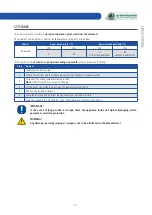
Page 81: ...81 TROUBLESHOOTING ...

Page 82: ......

Reviews: