22
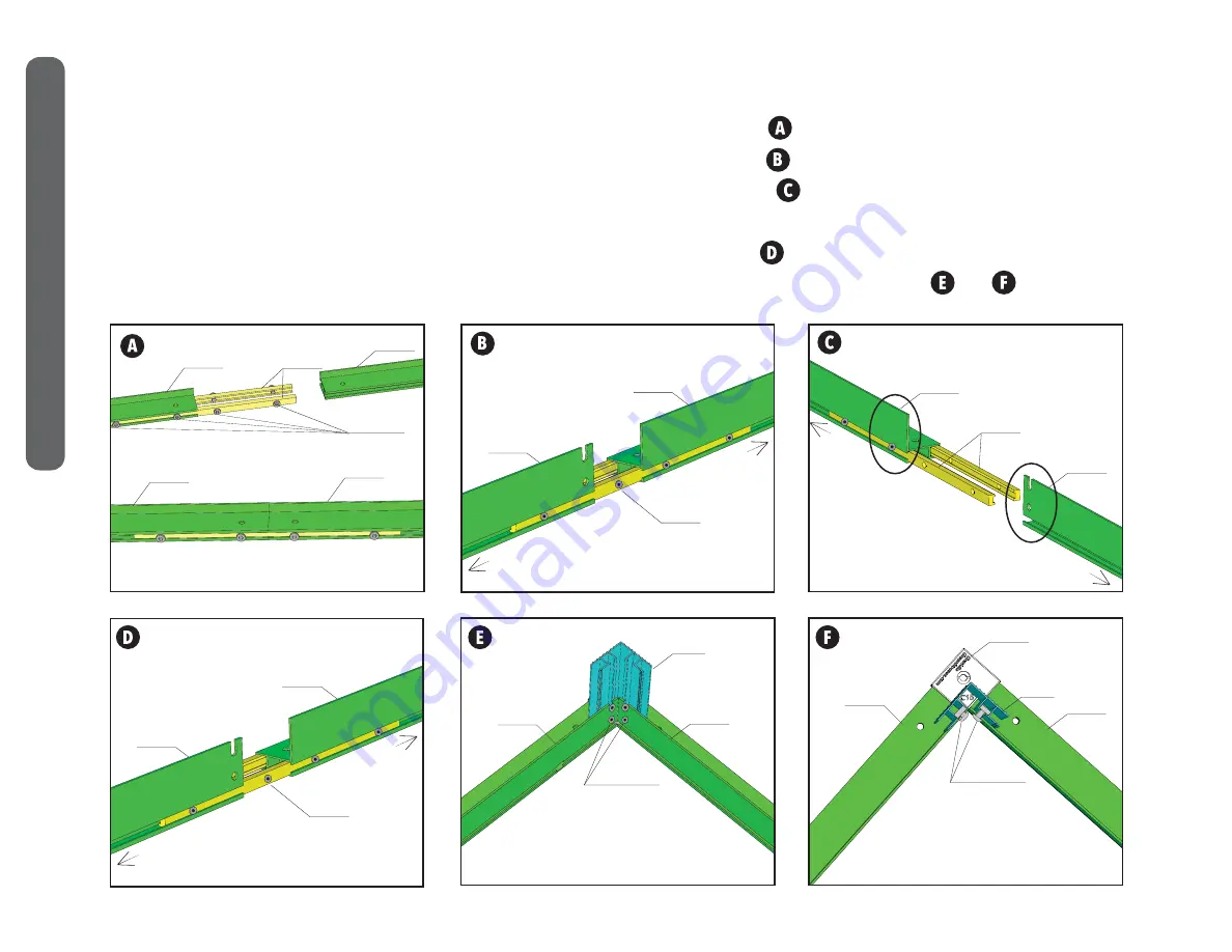
2. Connect the FRONT 12A and 12B pieces using the 14’s and the AFS-68 screws. See diagram .
3. Connect the BACK section 12C and 12D using the 14’s and the AFS-68 screws. See diagram .
4. Connect the RIGHT side 12C with the 12E using the 14’s and the AFS-68 screws, see diagram .
*REFER TO LAYOUT DIAGRAM ON PREVIOUS PAGE AS NEEDED.
5. Connect the LEFT side 12C with the 12D using the 14’s and the AFS-68 screws, see diagram .
6. Assemble the base kit as shown using the ABS-610 screws with the SQ-NUT-6 nuts at the 1C corners. See diagrams and .
12B
14
12A
FRONT EXTERIOR VIEW
CONNECTION OF 14 PARTS WITH SCREWS
AFS-68
FRONT
12A
12B
GRANDIO SUMMIT 12x12 FLAT MOUNT BASE ASSEMBLY
BACK INTERIOR VIEW
12C
12D
14
LEFT
RIGHT
LEFT INTERIOR VIEW
12C
12D
14
FRONT
BACK
INTERIOR CORNER VIEW
OF THE FLAT MOUNT BASE KIT
12D
12E
1C
ABS-610
SQ-NUT-6
BIRDS EYE CORNER VIEW
OF THE FLAT MOUNT BASE KIT
12D
12E
C15
1C
ABS-610
SQ-NUT-6
12C
12E
14
RIGHT SIDE INTERIOR VIEW
FRONT
BACK
12X12 FLA
T MOUNT
BASE


