51
12x24
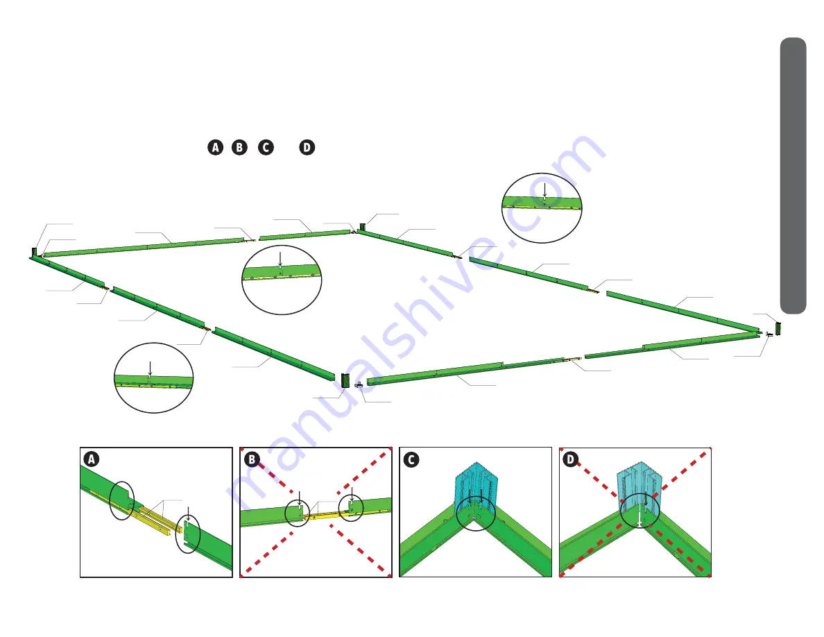
Flat Mount Base Kit Parts Laid Out
C14
12C
12D
14
12C
C14
C15
12C
12B
14
C15
12A
12G
12F
LEFT
BACK
RIGHT
FRONT
1C
1C
1C
1C
14
14
14
12F
14
12G
GRANDIO SUMMIT 12x24 FLAT MOUNT BASE ASSEMBLY
1. Lay out all of the parts exactly as shown in the diagram below. Confirm that the front is where you want your doors to be located. Be sure the
pieces are laid out exactly like the diagram, note that notches will have a 23” gap between each other, no notches should be right next to each
other except at the corners. See , , and to confirm you have the correct orientation prior to assembly.
NOTE: WRONG ORIENTATION!!
14
NOTE: WRONG ORIENTATION!!
INTERIOR CORNER VIEW
OF THE FLAT MOUNT BASE KIT
NOTE: CORRECT ORIENTATION
14
NOTE: CORRECT ORIENTATION
LEFT EXTERIOR VIEW
OF CONNECTIONS
NOTCH
BACK INTERIOR VIEW
OF CONNECTIONS
NOTCH
RIGHT INTERIOR VIEW
OF CONNECTIONS
NOTCH
12X24 FLA
T MOUNT
BASE


