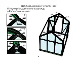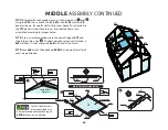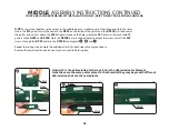
4.1
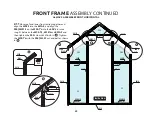
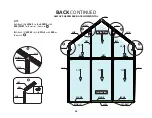
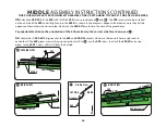
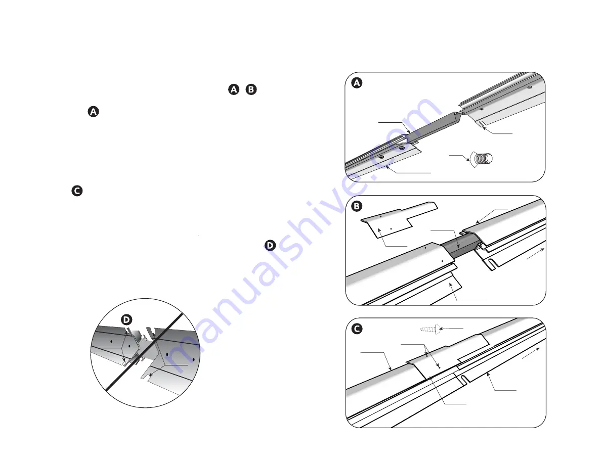
Attach the 607 to 607-4X extension with the
607-XS and the (4) S08 screws provided. See , . The
S08 screws are to be installed on the inside as shown in
diagram . Wait to tighten the screws all at one time
when both sections are aligned correctly, apply even
pressure while tightening.
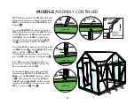
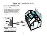
4.2
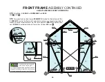
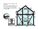
Apply a bead of silicone to the seam where the
607’s meet and to the holes where the S06 screws will
attach the DP01 to the 607 ridge.
See . Immediately align the DP01 apply a small
amount of silicone to the holes on the exterior of
DP01 then insert the S06 screws.
NOTE ORIENTATION OF THE NOTCHES, THEY
SHOULD BE SPACED ABOUT 2 FEET APART. SEE .
607-4X
607
607-XS
607-XS
607-4X
607
DP01
FRONT
S08
WARNING
Notches
Notches
APPLY SILICONE CAULK
TO RIDGE AND HOLES
S06
607
607-4X
FRONT
S06
DP01
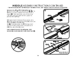
MIDDLE ASSEMBLY INSTRUCTIONS CONTINUED
THIS PAGE SHOWS 6X12 EXTENSION KIT ASSEMBLY ONLY, SKIP AHEAD TO PAGE 35 FOR 6X4 OR 6X8 SIZES.
35
Summary of Contents for Grandio Element 6x4 with Base Kit
Page 67: ...NOTES NOTES...

