7
4
A
1
2
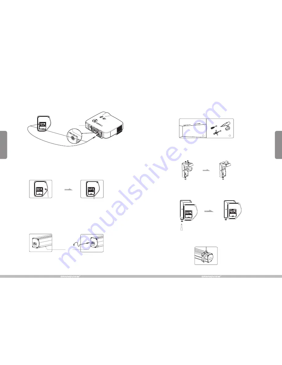
Figure 13
Figure 14
Figure 15
Figure 16
Figure 17
Figure 18
Figure 23
Figure 24
Figure 22
Figure 23
Figure 24
Projector
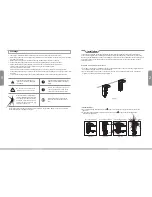
4.After completing steps 2 and 3, check to see whether the wall bracket is securely fixed onto the housing
of the screen before hanging. Hang screen as shown below. (figure 18)
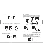
Ceiling Hang Installation
Choose tapping screws with hangers (or other screws with hangers, not provided) according to your
ceiling material. 5 x 40mm for wood ceilings and tapping screws for concrete ceilings are recommended.
1.Drill two identical holes with an electrical drill and ensure it is horizontal with the
Wall. Fasten hangers (not provided) into the ceiling (figure 13).
2.Use the M5 x 10 screws provided in the accessory package to fix the ceiling hanger into the wall bracket.
Ensure the tightening screws on the wall bracket are tightened and secure. (figure 14-15)
3.After inserting the ceiling hanger, ensure the grooves on the case housing match up with the mounting
bracket. To secure the case housing into the brackets, tighten the locking screws. (figure 16-17)
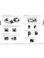
Automatic Trigger Control Description
1.Insert one end of the trigger wire into the trigger jack located on the left side of the screen casing's end cap
labeled
“
TRIG
”
. (figure 22). Insert the other end into the 12V output.
2.When the projector is powered on, the screen will lower automatically. When th projector is powered off, the
screen will retract automatically.
External Controls Description (Central Control or R232, Grandview Wall Switch)
Insert one end of the signal cord into the computer output jack located on the left side of the screen casing's end
cap and the other end of the signal cord to the central control jack, RS232 or Grandview wall switch. (figure 23-24).
You can then control the screen via central control or computer.
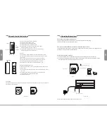
Infrared (IR) Remote Control Description
1.In order for the IR remote control to work, please ensure there is nothing covering the built-in sensor on the
screen casing.
For installations where the built-in sensor on the screen casing will be covered, use the external IR receiver
(provided) and insert it into the external IR slot on the screen casing's left end cap. Ensure the external IR
received head is in a position where it can received the remote control signal.
External IR sensor
External IR slot


