5
8
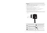
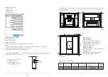
Installation steps
1
.
determine the direction of the projector and the installation position, according to the size
of the opening in the ceiling layer.
Concrete base
Concrete base
Ceiling decorative layer
(Ceiling opening size diagram)
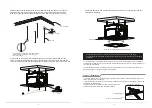
2
.
Punch the concrete base and install the Tapping screws.
Tapping screws
620m
m
310
mm
655mm
655
mm
Angle adjustment
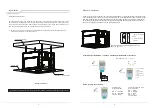
Electrical, product instructions
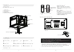
Control panel description
Up: Electric hanger rises
Stop: electric hanger stops
Down: electric hanger drop
Communication port: Category 6 network port
Dry contact: dry contact interface RS485: RS485 interface
Power input: power input interface
Fuse: F6. 3A 250V
Reset: long press the reset button to adjust the height
Memory: electric hanger memory position height
HDMI 2.0: 19+1 2.0 HD interface
Digital display: electric hanger current screw telescopic height
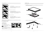
Rotate left and right ±3°
1
.
Rotate left and right
Use a hex wrench to loosen the two screws on the front end.
As shown by the arrow in Figure 1, the universal joint can be
adjusted to the left and right by ±3°.
2
.
vertical up and down adjustment
As shown in Figure 2, use the hex wrench to loosen the two
screws on the left and right. The universal joint can be adjusted
vertically upward by 1° and vertically downward by 8°.
。
3
.
The installation foot adjustment
Use a hex wrench to loosen the screws on the mounting feet.
As shown in Figure 3, adjust the screws to the desired length
and retighten the screws.
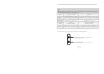
figure
1
1° vertically upwards and 8° vertically downwards
Adjust the length of the mounting feet
figure
2
figure
3
CONTROLLER
G1
up
CAT6
CAT6
Dry contact
RS-485
IN
-
220V 50Hz
INPUT
HDMI2
.
0
stop Down Reset memory

