2.3.1
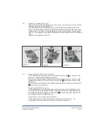
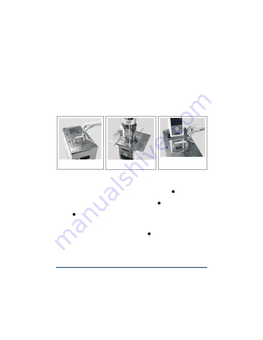
Assembly - All models (see Fig 1)
Remove the thermostat mounting plate from the tank by unscrewing the four black knobs
located in the corners of the plate (1a).
Feed the Optima thermostat through the hole in the bridge plate, being careful not to
force it. The thermostat can be located either facing forward or facing to the left. In either
position three of the holes in the mounting plate will line up with holes in the thermostat
unit (1b). Screw together using M3x6 stainless steel screws supplied with the thermostat
unit.
Reattach mounting plate to unit (1c).
2.3.2
Power Supply R1, R2, R3 (see Fig 3a/3b)
Power Supply R4,R5 (see Fig 3c)
Power Supply - 115v models (see Fig 3d/3e/3f)
The Thermostat unit takes its power from the mains socket outlet ( ) on the rear of the
cooler unit, via the interconnecting power cable.
Plug one end of this interconnecting cable into the power inlet socket on the rear of the
Thermostat unit and the other end into the socket outlet ( ) mounted on the rear of the
cooler unit.
Plug the mains cable (supplied with Optima thermostat) into the fused power inlet socket
( ) on the rear of the cooler unit.
The Thermostat unit is connected from the twin fused power inlet socket directly to the
mains with the IEC cable supplied with the Optima Thermostat. The refrigeration unit is
connected from the twin fused power inlet socket ( ) directly to the mains with the IEC
cable supplied with the Refrigeration unit.
The Thermostat unit is connected via its power cord directly to the mains . The
refrigeration unit is connected via its power cord directly to the mains.
Fig 1a
Fig 1b
Fig 1c
screw
screw
screw
Page 7
Low temperature bath/circulator
Operating instructions
Version 4 - Jan 2010
2
2
3
3


