background image


CRF-1 Operating Manual 

Page  22  of  60 

33801-V4 DMN S90 


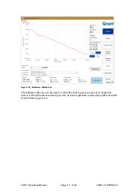
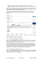
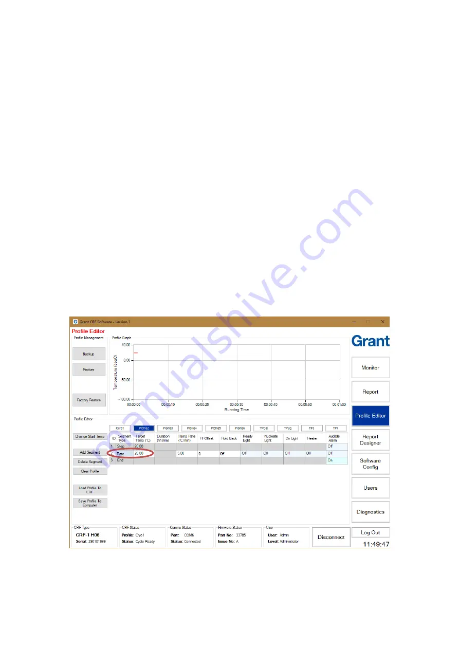
Figure 20: Software: Profile Editor 

6.5.1.  Editing an existing profile 

 
The following sections provide information about how to change cooling profiles. 
 

Note: When connected to a CRF-1 the changes made in the software are applied immediately 
to the cryocooler. Backups of all profiles or individual profiles should be created before 
making any significant changes. 


6.5.1.1.  Changing the start temperature 

Note: It is only possible to have one start temperature for all profiles and changing this value 
will update all profiles. Care and consideration should be taken before changing this 
parameter. 

 
Click 

Change Start Temp

 to change the universal profile start temperature. Update the 

Start 

Temp

 box with the required value and click 

Set Temp

 in the 

Set Start Temp

 dialog box. Click 

OK

 in the 

Confirm

 dialog box to apply the change to all profiles. 


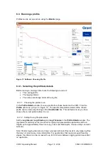
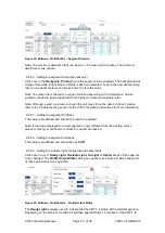
6.5.1.2.  Adding a segment 

Click the segment 

ID 

box to highlight the segment position


where the new segment is to be 

placed. Click 

Add Segment

. A new 

Rate

 segment will always be added after the segment 

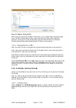
that is highlighted (see Figure


21) except when the last segment is selected, in which case 

the new segment is added before the end. The segment type can be changed after the 
segment has been added. 


Figure 21: Software: Profile Editor 

– Adding Segment 


Summary of Contents for CRF-1 H00

Page 1: ...Controlled Rate Freezer CRF 1 Series Operating Manual...

Page 2: ...report 19 6 4 2 Running a TSV log file conversion 20 6 4 3 Generating an event log report 21 6 5 Editing and creating profiles 21 6 5 1 Editing an existing profile 22 6 5 2 Setting the parameters of...

Page 3: ...8 5 Spermatozoa Cryopreservation Linear Cooling 46 8 6 Oocyte Non Linear Cooling Cryopreservation 47 8 7 Cryovial Cryopreservation 48 8 8 Test and Calibration profiles 48 9 Scientific References 49 1...

Page 4: ...re Connect 16 Figure 16 Software Status bar 17 Figure 17 Software Choosing Profile 18 Figure 18 Software Generating PDF Reports 20 Figure 19 Software Generating TSV Report 20 Figure 20 Software Profil...

Page 5: ...49 Pre programmed blastocyst freezing cycle 45 Figure 50 Pre programmed embryonic stem cell freezing cycle 46 Figure 51 Pre programmed sperm linear freezing cycle 46 Figure 52 Pre programmed oocyte n...

Page 6: ...ol CRF 1 CARTRIDGE Cryopen spare cartridges Brief operating instructions for these product accessories are given in Appendix 2 Please refer to accessory manuals for full operating instructions 2 How t...

Page 7: ...nsport or storage in humid conditions allow the unit to dry out before connecting it to the supply voltage Only connect the unit to the mains supply using the power supply unit and cables provided Ens...

Page 8: ...ryobank 96 2D tube system 374084 FluidX data matrix tube 96 65 52319 CRF 1 H06 Plate for 55 1 8ml cryovials Max working volume per vial is 1 0 ml NUNC cryovials 363401 round NUNC cryovials 377267 star...

Page 9: ...place hands underneath the unit and do not move by pressing on the casework 5 2 Freezer Position Ensure the freezer is positioned on a flat stable surface so that the vents and the air outlet at the...

Page 10: ...irectly from the mains supply To ensure run data is not lost check the power settings do not allow the laptop to go into standby or hibernation mode Do not close the laptop during a data run as this c...

Page 11: ...7 or Windows 10 In addition to loading the Grant CRF software you will also be loading the drivers for the USB to serial converter FTDI In the case of Windows 7 only you will be loading Microsoft NET...

Page 12: ...control Select Yes Figure 5 Software NET Framework Installation User Account Control Installation of the NET framework takes several minutes To complete the installation of NET your computer will rest...

Page 13: ...xtract the FTDI drivers These are required for the USB to serial converter that you will use to make the hardware connection to the CFR Select Extract Then on the following Device Driver Installation...

Page 14: ...ing Grant CRF Software from the program list in the start menu on your computer Figure 11 Desktop shortcut icon When the software is run for the first time the default User ID is Admin and the default...

Page 15: ...or changing towards the Set Temp o C While the CRF 1 is changing it is not possible to run a temperature profile and the Start button and Profile Details are disabled When the value in the Plate Temp...

Page 16: ...er will also be displayed If the software fails to connect to the unit see Appendix A1 3 for help Figure 15 Software Connect The freezer unit will remain connected until the Disconnect button is press...

Page 17: ...MN S90 Figure 16 Software Status bar The software suite can now be used to control the freezing cycle as well as configure the freezer edit and create new freezing cycles as well as generate reports w...

Page 18: ...the chosen profile can be viewed by clicking on the View Details box This will help ensure you have chosen the correct profile before it is run 6 3 1 2 Setting the log file parameters Set the Log Inte...

Page 19: ...on and are suitable for validation and archiving purposes Four reports can be produced from the encrypted log file using the Report page PDF Detailed Report Includes a graph of the actual and set temp...

Page 20: ...e location using the dialog box which appears see Figure 19 Note The TSV will not appear in the viewing area Figure 19 Software Generating TSV Report 6 4 2 Running a TSV log file conversion Click GEF...

Page 21: ...etails 6 5 Editing and creating profiles The CRF 1 is configured with a standard set of profiles specific to the model type but the software provides a great degree of flexibility in programming new p...

Page 22: ...ofiles Care and consideration should be taken before changing this parameter Click Change Start Temp to change the universal profile start temperature Update the Start Temp box with the required value...

Page 23: ...ers can be easily met The maximum or minimum parameter values for a segment represent the highest or lowest value that can normally be achieved Any profile created or modified should be tested to conf...

Page 24: ...only Click once in the Target Temp o C box of the segment to be changed The background will change from white to light blue to indicate it has been selected Type in the new desired target temperature...

Page 25: ...it please refer to the Troubleshooting section of the CRF 1 Operating Instructions for more information 6 5 2 7 Setting the segment FF offset This value is predefined and should not need to be altered...

Page 26: ...for any segment type 6 5 2 10 Setting the audible alarm Click once in the Audible Alarm box of the segment to be changed The Alarm Editor dialog box will appear Choose whether to set the alarm to sou...

Page 27: ...ntly the previous profile stored Care and consideration should be taken before loading profiles as information can be lost Click Load Profile To CRF 1 The Open dialog box opens in the default profiles...

Page 28: ...ent window to restore a backup of all of the profiles Select the backup to restore from the list in the Open dialog box and click Open The Restore Profile Selection dialog box opens see Figure 29 Tick...

Page 29: ...ing and configuring reports The reports created are based on a standard template that can be customised via the Report Designer page 6 6 1 User defined report header The Report Template has two header...

Page 30: ...g Manual Page 30 of 60 33801 V4 DMN S90 Figure 30 Software User Defined Report Header These user defined conditions will appear at the top of a generated report see Figure 31 Figure 31 Software User D...

Page 31: ...d to suit your file set up and can be a network share Click on the Browse For Folder button next to the Default Dir option to choose a new location see Figure 32 Figure 32 Software Log File Configurat...

Page 32: ...e ensure that the Include Text box in the Log window on the Software Config page is checked see Figure 34 When the Include Text box is checked a User Text box next to the Log Filename box on the Monit...

Page 33: ...e default storage folder for saved profiles This location can be varied to suit your file set up and can be a network share Click on the Browse For Folder button next to the Default Dir box to choose...

Page 34: ...be created when logged on as Admin or another administrator level user Click Users to open the Users page The first user in the list will be highlighted in blue and the User Details for that user will...

Page 35: ...required information and click Update Be sure not to edit the Administrator s User Level If there is no user with Administrator permissions it will be necessary to reinstall the software to make signi...

Page 36: ...to prepare and use it Alternative tools for nucleating e g forceps may be used if sterility of the operating environment is not essential 7 3 Sample Preparation Before preparing samples remove the li...

Page 37: ...such that the samples are in the centre of the freezing plate the straw plug should overhang the freezing plate if required Figure 37 0 25ml IMV straws positioned on sample plate 7 3 1 3 CRF 1 H02 1 8...

Page 38: ...ample plate Figure 39 SBS microplate positioned on sample plate Once in position place the lid over the sample plate checking that it is located correctly 7 3 1 6 CRF 1 H06 1 8ml Cryovials 1 0ml max f...

Page 39: ...ture of the plate is logged automatically in an encrypted format The data is stored in the file location shown on the Monitor panel At the end of the cycle the data can be used to create a report or a...

Page 40: ...on plateau temperature the time displayed changes to Nucleate The freezer unit buzzer sounds and the yellow Nucleate light on the freezer unit illuminates Nucleation should be done at this time The pr...

Page 41: ...ne second Figure 43 Figure 44 Figure 45 Repeat with the remaining samples and replace the lid of the freezer Note that other methods of ice nucleation may also be employed dependent on experimental pr...

Page 42: ...data will continue to be logged 7 7 Stopping the Cycle and Generating a Report When all of the vessels have been transferred click on the Stop Cycle button on the software Monitor panel Temperature lo...

Page 43: ...d stabilised at the start temperature the Cryocooler Status will change to Cycle Ready The Start Cycle button will no longer be greyed out and more samples can be loaded in preparation for another fre...

Page 44: ...20 C Cool from 20 C to 7 C at 2 C min 1 Hold for nucleation at 7 C for 10 minutes Cool from 7 C to 30 C at 0 3 C min 1 Cool from 30 C to 33 C at 3 C min 1 Cool from 33 C to 39 C at 6 C min 1 Cool fro...

Page 45: ...rogrammed oocyte freezing cycle 8 3 Blastocyst Cryopreservation Profile name Blasto Applicable models H00 H01 H03 H07 H08 Start temperature 20 C Cool from 20 C to 7 C at 1 C min 1 Hold for nucleation...

Page 46: ...tozoa Cryopreservation Linear Cooling Profile name Sperm Applicable models H00 H01 H03 H07 H08 Start temperature 20 C Cool from 20 C to 7 C at 2 C min 1 Hold for nucleation at 7 C for 10 minutes Cool...

Page 47: ...l from 18 1 C to 22 2 C at 0 4 C min 1 Cool from 22 2 C to 25 3 C at 0 3 C min 1 Cool from 25 3 C to 27 8 C at 0 2 C min 1 Cool from 27 8 C to 31 C at 0 1 C min 1 Cool from 31 C to 34 C at 3 C min 1 C...

Page 48: ...ure 53 Pre programmed cryovial freezing cycle 8 8 Test and Calibration profiles Profile name TCal TP1 TP2 Applicable models H00 H01 H03 H07 H08 Profile name TP3 TP4 Applicable models H02 H05 H06 These...

Page 49: ...gen and laminin on the cryopreservation of human embryonic stem cells Stem Cells 22 950 961 Lasalle P Testart J and Renard JP 1985 Human embryo features that influence the success of cryopreservation...

Page 50: ...spilt onto the equipment disconnect it from the power supply and have it checked by a competent person It is the user s responsibility to carry out appropriate decontamination if hazardous material i...

Page 51: ...ons 2006 We are a member of the B2B compliance scheme Scheme Approval Number WEE MP3338PT SCH which handle our WEEE obligations on our behalf Grant Instruments have been issued with a unique registrat...

Page 52: ...power lead is not properly connected to the unit Check the power lead is properly connected into the rear of the unit There is no power to the power lead Check the power lead is plugged into a socket...

Page 53: ...mples are dry before freezing Section 7 3 Samples can be removable with careful use of tweezers Appendix 2 Cryopen Nucleating Tool Operation Please read the instruction manual supplied with the cryope...

Page 54: ...used Follow the instructions below Take the mini CD supplied with the converter and insert it into the CD DVD drive of your PC Follow the on screen instructions Insert the converter into a USB socket...

Page 55: ...ng Manual Page 55 of 60 33801 V4 DMN S90 This should be used when setting the COM port in the Software Config panel of the User Software Suite See Figure 55 Figure 55 Configuring the Com Port on the U...

Page 56: ...a finger into the top hole and pulling it gently but firmly upwards 2 Once the top foam is removed the unit can be gripped by the bottom foam hand hold and with one hand on the sample plate 3 Grasp t...

Page 57: ...nit on the foam with the cut corners of the foam facing forwards as shown 3 Tighten the strap until it is taut Place the buckle as shown Avoid the buckle touching the unit 4 Fit top foam piece as show...

Page 58: ...GE AND MAY VOID THE PRODUCT WARRANTY 1 Place unit carefully on a secure surface with the switch and keypad facing upwards to remove the transit bolt 2 Attach blanking plate supplied re using black thu...

Page 59: ......
Page 60: ...opean Union Shepreth Grant Instruments Europe B V Cambridgeshire Strawinskylaan 411 SG8 6GB WTC Tower A 4th Floor UK 1077 XX AMSTERDAM THE NETHERLANDS Tel 44 0 1763 260811 salesdesk grantinstruments c...

Reviews: