Hydraulic Connections
39
8
Hydraulic Connections
12
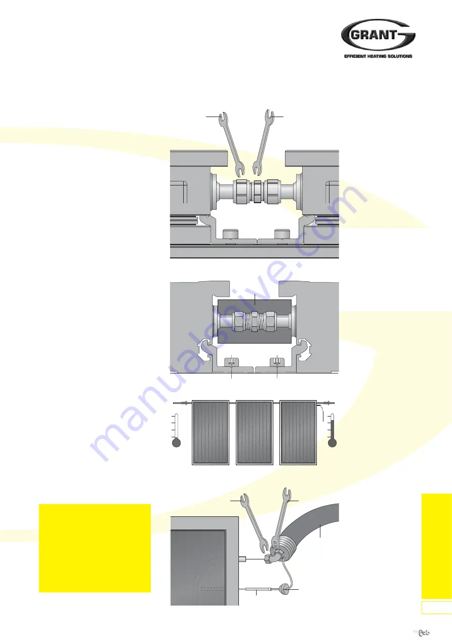
Figure 89:
Fit Thermal Installation
Figure 90:
Solar Collector Field Attachment
Figure 91:
Connection of Temperature Sensor
8.1 Compression Connection,
Straight
1. Tighten the nuts on the
compression connection (11).
Caution:
Apply opposite force when
tightening the compression
connection, otherwise the pipes on
the solar collector can be damaged!
2. After successfully checking the seal
of the solar collectors, place
thermal insulation (12) around the
hydraulic connection, and remove
the protective film from the adhesive
strip to secure it in place.
3. Continue in the same way to install
additional solar collectors.
4. Inlet connection (A) and outlet
connection (B) for the solar collector
field is left to the installer to choose.
Caution:
Locate the solar collector
temperature sensor (19) in the
sensor pocket next to the Outlet
(flow) connection of the collector
array.
5. Push back the thermal insulation on
the solar collector connection kits,
place the compression connections
onto the connectors and secure.
6. Take the temperature sensor seal
(13) out of the solar collector hole
next to the outlet (flow) connection,
pierce the centre and push it over
the temperature sensor. Finally,
guide the temperature sensor fully
into the sensor pocket of the solar
collector and seal by re-inserting
the temperature sensor seal.
Caution:
Push the solar collector
temperature sensor to the end of
the hose sleeve so that the correct
measuring point is reached.
19mm
17mm
19mm
14mm
19
01
01
01
01
19
A
B
Figure 88:
Hydraulic Connection
13
06
Important:
All system pipe connections must
use compression fittings with
brass olives. Soft soldered joints
must NOT be used on the solar
primary circuit.
Plastic pipe must NOT be used
for any part of the solar primary
circuit.
For latest prices and delivery to your door visit MyTub Ltd - www.mytub.co.uk - info@mytub.co.uk 0844 556 1818


