18
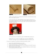
3. Place one of the jubilee clips provided over the end of the tube. Fold the anti-static wire back
inside the tube. Refer to Figure 4-21.
4. Push the tube fully onto the ‘VACUUM RETURN’ connection spigot (on the vacuum unit),
ensuring that the anti-static wire is in contact with the unpainted steel surface of the connection
spigot. Tighten the jubilee clip to secure the tube in place and clamp the anti-static wire to the
spigot. Refer to Figure 4-22.
5. Connect the other end of the flexible tube to the ‘VACUUM RETURN’ on the auger unit.
6. Repeat this process using the second flexible tube to connect the ‘VACUUM FLOW’
connection (on the auger unit) to the ‘VACUUM FLOW’ connection (on the vacuum unit).
If the vacuum unit operates but no pellets are delivered to the hopper from the store:
•
Switch the ‘VACUUM SYSTEM’ ON/OFF switch to OFF.
•
Isolate the electrical supply to the boiler and SpiraVac system.
•
Check that two flexible tubes between the vacuum unit and auger unit are correctly connected.
•
Rectify any incorrect ‘cross connections’
•
Reconnect the power supply, Switch the ‘VACUUM SYSTEM’ ON/OFF switch to ON and check
that the SpiraVac system operates correctly.
Figure 4-22. Tube secured with clip
Figure 4-20. Anti-static wire exposed
Figure 4-21. Anti-static wire folded in
Summary of Contents for WPVKIT10
Page 12: ...12 Figure 3 6 SpiraVac operation flow diagram ...
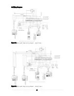
Page 22: ...22 Figure 5 4 Vacuum unit wiring diagram ...
Page 24: ...24 Figure 5 6 Heating system controls S plan type system connection diagram ...
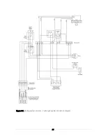
Page 25: ...25 Figure 5 7 Heating system controls Y plan type system connection diagram ...


