19
5. Electrical
5.1 General
The electrical installation, including internal and external wiring and supplementary earth bonding, must
be installed by a competent person to comply with the requirements of the Electricity at Work Regulations
1989 and BS7671:2008 – IET Wiring Regulations 17
th
Edition (including all amendments).
5.2
Connection to Pellet Hopper
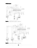
The electrical supply to the boiler (and SpiraVac system) is connected to the pellet hopper. Refer to either
Figure 5-2 (for single boiler hopper) or Figure 5-3 (for double boiler hopper) for the electrical wiring
diagram for the pellet hopper.
The Grant Spira pellet boiler and SpiraVac system requires a 230V ~ 50 Hz supply. This must be
supplied via a 13A fused double pole isolator, providing complete electrical isolation for the heating
control system, Spira hopper/boiler and SpiraVac system.
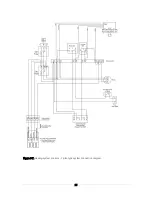
A second fused double pole isolator is required to provide a 5A fused supply to the boiler and heating
control system only. Refer to Figure 5-6 for the wiring details with an S-plan type heating control system.
The power supply cable to the hopper should be at least
1.5mm² PVC.
Refer to the main Installation Instructions, supplied with the boiler, for further details on the wiring of the
electrical system controls and the other electrical connections on the boiler to be made during
installation.
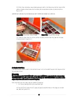
Note: The hopper is fitted with a selector switch (located inside the wiring centre). Ensure that this switch
is set to the ‘BULK STORE’ position when connecting the 6-way pre-wired plug from the hopper to the
Vacuum unit. See Figure 5-1.
Figure 5-1. Location of selector switch (inside hopper wiring centre)
5.3
Connection of Vacuum Unit to Pellet Hopper
The vacuum unit is supplied with two factory-fitted flying leads with pre-wired plugs.
The 6-way plug and lead connects the vacuum unit to the pellet hopper. Connect this plug to the
corresponding 6-way connector (to be found within the electrical wiring enclosure at the rear of the pellet
hopper). Refer to Figure 5-1 for location of 6-way connector.
6-way connector (docked on
the contents switch bracket)
Selector switch
Summary of Contents for WPVKIT10
Page 12: ...12 Figure 3 6 SpiraVac operation flow diagram ...
Page 22: ...22 Figure 5 4 Vacuum unit wiring diagram ...
Page 24: ...24 Figure 5 6 Heating system controls S plan type system connection diagram ...
Page 25: ...25 Figure 5 7 Heating system controls Y plan type system connection diagram ...


