30
8. User Instructions
8.1 Introduction
This information is intended to assist the User in the operation of the Grant SpiraVac wood pellet supply
system when used in conjunction with a Grant Spira wood pellet boiler.
These instructions must be read and used in conjunction with the User Instructions supplied with the
Grant Spira wood pellet boiler.
The Installers information for the installation and maintenance of this vacuum system is covered in
Sections 1 to 7 of these Installation & User Instructions.
8.2 About the Grant SpiraVac system
The vacuum unit (mounted on the top of the pellet hopper) is connected to the auger unit (mounted on
the bulk pellet store) by two flexible tubes.
When the level of the pellets in the pellet hopper falls to a minimum level the contents switch (built into the
hopper) is activated. This in turn starts the vacuum motor in the vacuum unit and also the auger in the
auger unit. The auger pulls pellets from the base of the pellet store and the vacuum draws the pellets
through the suction flow tube to the vacuum unit.
Here the pellets are collected in the cyclone unit (beneath the vacuum unit - within the pellet hopper).
After running for 75 seconds the vacuum motor stops. The trap door at the base of the cyclone opens
and the pellets stored within fall into the hopper.
This process will be repeated several times until the hopper is filled with pellets up to the level of the trap
door of the cyclone. In this condition the trap door will be prevented from closing by the pellets. This is
intentional as further operation of the vacuum system is not required with this amount of pellets in the
hopper. Refer to the flow diagram in Figure 3-6 for further information on the Grant SpiraVac operation.
8.3 Controls
The vacuum unit has a control panel with fitted with a ‘VACUUM SYSTEM’ ON/OFF switch and
RED
INDICATOR NEON
. Refer to Figure 8-1.
Figure 8-1. Vacuum system control panel
Vacuum system ON/OFF Switch
When the ‘VACUUM SYSTEM’ switch is set to ON the small red neon (on the switch) will be lit. The
vacuum system is operational and will automatically start when the contents switch (in the hopper)
detects the minimum pellet level.
When the ‘VACUUM SWITCH’ is switch is set to OFF the small red neon on the switch will not be lit and
the vacuum system will NOT be operational.
Summary of Contents for WPVKIT10
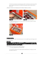
Page 12: ...12 Figure 3 6 SpiraVac operation flow diagram ...
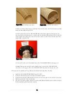
Page 22: ...22 Figure 5 4 Vacuum unit wiring diagram ...
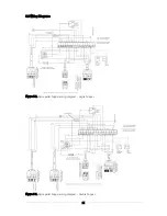
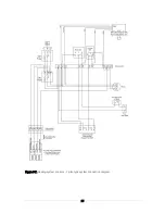
Page 24: ...24 Figure 5 6 Heating system controls S plan type system connection diagram ...
Page 25: ...25 Figure 5 7 Heating system controls Y plan type system connection diagram ...


