8
The vacuum unit has two factory-fitted flying leads with pre-wired plugs.
•
The 6-way plug connects the vacuum unit to the pellet hopper, via the corresponding factory
fitted flying lead and pre-wired 6-way connector (to be found within the electrical wiring enclosure
at the rear of the pellet hopper).
•
The 3-way plug provides the electrical connection for the remote auger unit. A suitably sized
cable of the required length must be connected between the corresponding 3-way connector
(supplied fitted to the plug) and the electrical isolator of the remote auger (mounted on the bulk
pellet store). Refer to Figure 5-5.
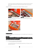
The vacuum unit has a control panel fitted with a ‘VACUUM SYSTEM’ ON/OFF switch and indicator neon.
Refer to Figure 3-3.
Figure 3-3. Vacuum unit control panel
For details on the operation of these controls, refer to the User Instructions in Section 8 of these
Installation & User Instructions.
3.2 Auger Unit
The auger unit has been designed to be mounted directly onto the Grant bulk pellet store (with the fixings
supplied on the store) using the holes already present around the rectangular outlet opening at the base
of the store. It can also be fitted to other bulk pellet stores by drilling the required holes (using the auger
mounting flange as a template) – refer to Section 4.1.
The unit consists of a 410mm long auger, driven by an electric motor, which delivers pellets into the
suction chamber. Refer to Figure 3-5.
Two steel connection spigots are provided, on the end of the suction chamber, for connection of the
vacuum system flexible tubes. Refer to Figure 3-5. The auger motor and suction chamber are enclosed
beneath a removable steel cover, held in place by two nuts.
A 3-pole 16A isolator is factory fitted to the auger unit for local isolation of the auger motor when required.
This isolator is pre-wired to the auger motor. An electrical supply, from the 3-way plug on the vacuum
unit, must be connected by the installer to the input of the isolator. Refer to Section 5 for electrical
connection details.
Summary of Contents for WPVKIT10
Page 12: ...12 Figure 3 6 SpiraVac operation flow diagram ...
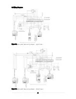
Page 22: ...22 Figure 5 4 Vacuum unit wiring diagram ...
Page 24: ...24 Figure 5 6 Heating system controls S plan type system connection diagram ...
Page 25: ...25 Figure 5 7 Heating system controls Y plan type system connection diagram ...


