18
CONSTRUCTION AND USE
The impact driver is a battery-powered tool.
The drive consists of DC commutator motor
with permanent magnets. The impact driver
is used for tightening and undoing screws and
bolts in wood, metal or plastics. High speed
allows to use the device widely for self drilling
screws, and high torque allows to use the
device for long screws in wood. The device can
be well used at heights and in hard to reach
areas. High torque mechanism creates the
torque as short, high peaks of circumferential
impact, and tool reactions towards the
operator's hands during tightening is low.
Use the power tool in accordance with the
manufacturer’s instructions only.
DESCRIPTION OF DRAWING PAGES
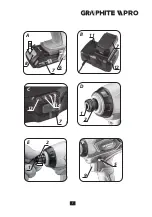
Below enumeration refers to the device
elements depicted on the drawing pages of
this manual.
1.
Tool chuck
2.
Fixing sleeve of the tool chuck
3.
Casing
4.
Handle
5.
Direction selector switch
6.
Holder
7.
Battery
8.
Battery lock button
9.
Switch
10.
Lighting
11.
LED diodes
12.
Charger
13.
Button for battery level indication
14.
Battery level indicator (LED)
* Differences may appear between the product and
drawing..
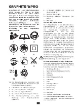
MEANING OF SYMBOLS
CAUTION
WARNING
ASSEMBLY / SETTINGS
INFORMATION
EQUIPMENT AND ACCESSORIES
1.
Battery
- 2 pcs
2.
Charger
- 1 pce
3.
Driver bits
- 1 pce
4.
Carrying case
- 1 pce
PREPARATION FOR OPERATION
REMOVING AND INSERTING THE BATTERY
•
Set the direction selector switch (
5
) in
middle position.
•
Push the battery lock button (
8
) and slide
out the battery (
7
) (
fig. A
).
•
Insert charged battery (
7
) into the handle
holder, you should hear when the battery
lock button (
8
) snaps.
BATTERY CHARGING
Batteries are supplied in partially charged
condition. The battery should be charged in
ambient temperature between 4°C and 40°C.
New battery, or one that has not been used
for a long time, will reach full efficiency after
approximately 3 to 5 charge/discharge cycles.
•
Remove the battery (
7
) from the power tool
(
fig. A
).
•
Connect the charger to mains socket (
230
V AC
).
•
Slide the battery (
7
) into the charger (
12
)
(
fig. B
). Ensure the battery is properly fitted
(pushed to the end).
After battery is placed inside the charger,
various combinations of diodes will light up
(see description below).
• Green diode on –
indicates voltage on the
connector.
• Green diode on, red diode flashing (1 per
second) –
battery charging in progress.
• Green and red diodes on –
the battery is
fully charged.
• Green diode on, red diode flashes (3 times
per second) –
the battery temperature is
too high (above 45°C) or battery is damaged
and requires replacement.
When the battery temperature rises too
much during a recharge (above 45°C) and
recharge is stopped (red diode flashes
Summary of Contents for 59GP402
Page 2: ...2...
Page 4: ...4...
Page 6: ...6 2 1 10 9 8 3 5 4 6 7...
Page 7: ...7 A 8 8 PRESS A 7 6 B 11 7 12 C 13 14 7 D 2 1 E 2 1 F 9 5...
Page 29: ...29 59GP402 50o C 0o C 30...
Page 30: ...30 Li Ion...
Page 31: ...31 Li Ion Li Ion 1 6 2 3 7 8 9 10 11 5 4 Max 50 C 1 2 3 4 5 6 II 7 8 9 10 11 1...
Page 34: ...34 2 E 1 2 2 D 5 F 5 5 5 5 3 6...
Page 37: ...37 59GP402 50o C 0 C 30...
Page 38: ...38...
Page 39: ...39 1 6 2 3 7 8 9 10 11 5 4 Max 50 C 1 2 3 4 5 6 7 8 9 10 11 Recykling 1 2 3...
Page 42: ...42 2 D 5 F 5 5 5 5 3 6 18 Li Ion 2500 A USB Power Bank 5 1...
Page 96: ...96 50o C 0o C 30...
Page 97: ...97...
Page 101: ...101 5 F 5 5 5 5 3 6 18V DC Li Ion 2500 mAh USB Power Bank 5 V DC 1A 2800 min 1 6 35 mm 165 Nm...
Page 116: ...116 59GP402 50 C 0o C 30...
Page 117: ...117 Li Ion...
Page 118: ...118 Li ion Li Ion 1 6 2 3 7 8 9 10 11 5 4 Max 50 C 1 2 3 4 5 6 II 7 8 9 10 11...
Page 121: ...121 9 LED 10 9 2 E 1 2 2 D 5 F 5 5 5 5 3 6...
Page 145: ...145...
Page 146: ...146...
Page 147: ...147...
Page 148: ...graphite pl...


