1-8
Introduction
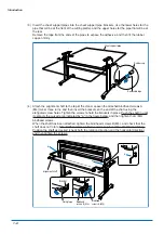
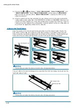
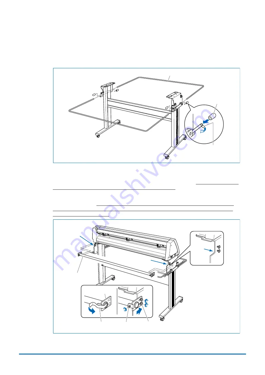
(3) Insert the sheet support pipes into the sheet support pipe brackets. Use the lower holes for the
pipe that will be at the front of the cutting plotter, and the upper holes for the pipe that will be at
the rear.
Remove the tape from the ends of the pipes to expose the adhesive, and then fit the rubber
caps on firmly.
Sheet support pipe
Rubber cap
Removable tape
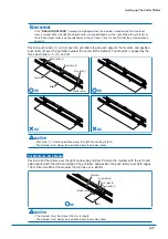
(4) Attach the alignment shaft to the top of the stand. Loosen the attached bindhead screws A
(M4) two or three turns, and then insert the brackets on the end of the shaft using the
elongated screw holes. Tighten the screws to hold the brackets in place. Push the shaft in until
it contacts the curved area indicated by "a" in the figure below, and then tighten the A (M4)
bindhead screws.
When the shaft has been attached, tighten the bindhead screws B (M4), and check that the
shaft does not rotate. The bindhead screws B are screws to prevent the shaft from rotating.
Position the shaft as desired (check both the rotation direction and the horizontal direction)
and then tighten the screws.
Bracket
a
a
a
Bindhead
screws A (M4)
Bindhead
screws B (M4)
Fixing tape
Alignment shaft

