CE5000-UM-251-9370
6-18
6. DISASSEMBLY AND REASSEMBLY
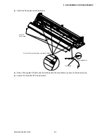
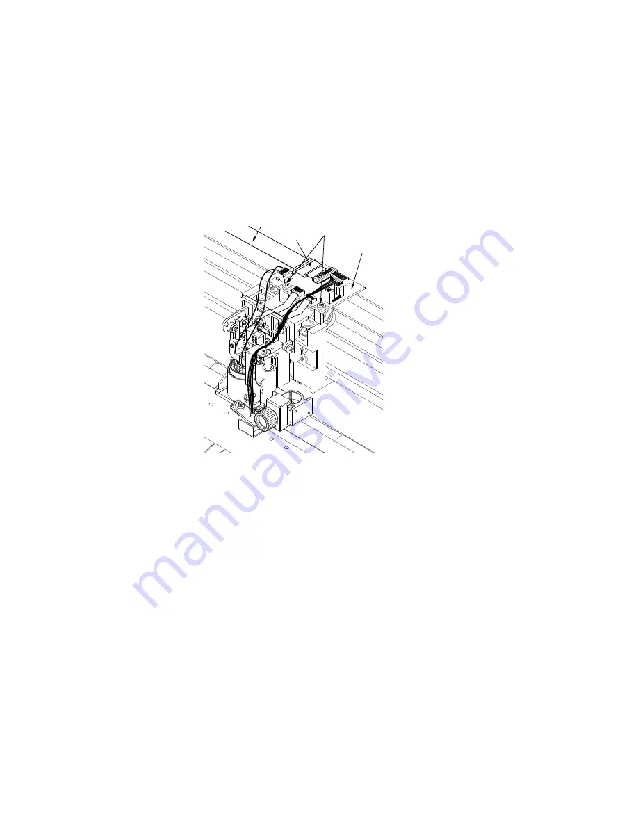
6.2.7 How to Replace the Y-relay Board
How to detach the Y-relay board
(1) Detach the center cover (see Subsection 6.1.3 or 6.1.4).
(2) Detach the pen block cover (see Subsection 6.2.5).
(3) Disconnect all the cables from the Y-relay board.
To disconnect the Y-flexible cable:
Remove the wiring harness tiewrap and detach the core attached with double-sided adhesive tape to the
Y-relay board.
(4) Remove the push roller sensor flexible cable attached with double-sided adhesive tape to the Y-slider.
Y-relay board
M3L6 binding head screw
Core
Y-flexible cable
(5) Remove the two M3L6 binding head screws attaching the Y-relay board.
How to reinstall the Y-relay board
(1) Reattach the Y-relay board in the reverse order in which it was detached.
Summary of Contents for CE5000-120
Page 1: ...CE5000 UM 251 09 9370 CE5000 Series SERVICE MANUAL MANUAL NO CE5000 UM 251 CUTTING PLOTTER...
Page 24: ......
Page 28: ...CE5000 UM 251 9370 3 4 3 OPERATIONS CE5000 120AP ENTER key ENTER key...
Page 34: ......
Page 36: ......
Page 72: ......
Page 90: ......
Page 96: ......
Page 100: ......
Page 116: ......

