CE5000-UM-251-9370
7-11
7. ELECTRICAL ADJUSTMENTS
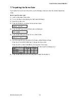
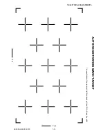
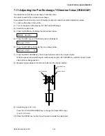
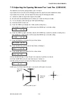
(11) Measure the offset between the printed cross mark and plotted cross mark.
Media feed
direction
Printed target mark
Cross mark
plotted by the
plotter
Y
X
+Y
-Y
+X
-X
(12) Set the offset value. Press the UP ARROW key or DOWN ARROW key to change the number.
Press the LEFT ARROW key or RIGHT ARROW key to change the digits of a number.
Press the ORIGIN key to select the X or Y direction.
Press the COND. key to select the + or - direction.
(13) Press the ENTER key to store the setting.
(14) Verify that the plotted cross mark line is located at the center of the printed cross mark line. Move the
pen to the printed cross mark area. Press the ENTER key to repeat the scan as described in step (10).
MARK ADJ SCAN
(15) Repeat steps (9) to (14) if the location of the plotted cross mark is incorrectly positioned. If the location of
the plotted cross mark is in the correct position, press the NEXT key and then turn off the power.
Summary of Contents for CE5000-120
Page 1: ...CE5000 UM 251 09 9370 CE5000 Series SERVICE MANUAL MANUAL NO CE5000 UM 251 CUTTING PLOTTER...
Page 24: ......
Page 28: ...CE5000 UM 251 9370 3 4 3 OPERATIONS CE5000 120AP ENTER key ENTER key...
Page 34: ......
Page 36: ......
Page 72: ......
Page 90: ......
Page 96: ......
Page 100: ......
Page 116: ......


