CE7000-UM-251-9370 3-5
3 PARTS NAMES and FUNCTIONS
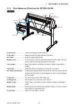
3.1.3 Parts Names and Functions for CE7000-130/160
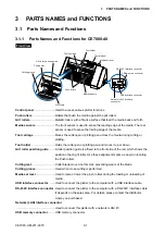
Front View
Cutting mat
Grit roller position guide
Cutting groove
Tool carriage
Tool holder
Control panel
Media set lever
Push rollers
Media sensors
Grit rollers
Media stopper
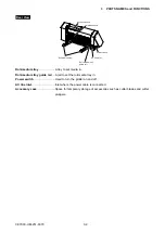
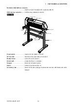
Power switch
Control panel
���������������������������Used to access various plotter functions�
Push rollers
������������������������������Rollers that push the media against the grit rollers�
Grit rollers
��������������������������������Feeds the media back and forth�
Media sensors
��������������������������The front sensor is used to sense the leading edge of the media� The rear
sensor is used to sense the trailing edge of the media�
Tool carriage
����������������������������Moves the cutter-pen or plotting pen across the media during cutting or
plotting�
Tool holder
�������������������������������Holds the cutter-pen or plotting pen and moves it up or down�
Grit roller position guide
���������A roller position guide is affixed to the front side of the rail, which shows the
position of each grit roller� Use these alignment marks as an aid in locating
the Push rollers�
Cutting mat
�������������������������������The cutter blade moves on this cutting mat�
Cutting groove
�������������������������Use this groove to cut out (die cut) or cross cut�
Media set lever
�������������������������Used to raise or lower the Push rollers during the loading or unloading of
media�
Media stopper
��������������������������This stops the stock shaft from spinning when setting in media� It is utilized
when pulling roll media straight out�
Power switch
����������������������������Used to turn the plotter on and off�
Summary of Contents for CE7000-130
Page 1: ...CE7000 UM 251 00 9370 CUTTING PLOTTER SERVICE MANUAL CE7000 40 60 130 160 130AP ...
Page 2: ......
Page 4: ...CE7000 UM 251 9370 II ...
Page 72: ...CE7000 UM 251 9370 5 2 5 RECOMMENDED PARTS LIST ...
Page 74: ......

