CE7000-UM-251-9370 VII
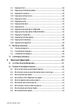
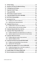
9 TROUBLESHOOTING ............................................................... 9-1
9.1 The Plotter is Turned On But Doesn’t Operate ................................................................... 9-1
9.2 Media Loading Operations ...................................................................................................9-2
9.3 Cutting Operations ...............................................................................................................9-5
9.4 Print & Cut Operation ........................................................................................................... 9-7
9.5 USB connection ...................................................................................................................9-11
9.6 Error Messages ....................................................................................................................9-12
9.6.1 Hardware Error Messages ...................................................................................................................9-12
9.6.2 Error Messages in GP-GL Command Mode .......................................................................................9-16
9.6.3 Error Messages in HP-GL Emulation Mode .......................................................................................9-19
9.6.4 Error Messages on ARMS .......................................................................................................................21
9.6.5 Other Error Messages .............................................................................................................................26
9.6.6 Warning Messages ..................................................................................................................................30
9.7.1 Sensor & Panel Switch Test Mode .........................................................................................................31
9.7.2 Printing the Setting of the Plotter ..........................................................................................................33
9.7.3 Printing the Test Pattern .........................................................................................................................34
9.7.4 Confirm the Cutting Data ........................................................................................................................35
9.7.5 Self Diagnostic Test .................................................................................................................................36
9.7.6 Registration Mark Sensor Test ...............................................................................................................38
9.7.7 Clear Setup Mode ....................................................................................................................................40
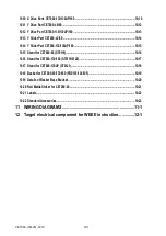
10 PARTS LIST ............................................................................. 10-1
10.1 Outer Casing CE7000-40/60 ................................................................................................10-1
10.2 Outer Casing CE7000-130/130AP/160 ................................................................................ 10-2
10.3 Additional Outer Casing CE7000-130AP ........................................................................... 10-3
10.4 Control Panel .......................................................................................................................10-4
10.5 Pen Block CE7000-40/60/130/160 .......................................................................................10-5
10.6 Pen Block CE7000-130AP ...................................................................................................10-6
10.7 Main Electrical Parts CE7000-40/60 .................................................................................. 10-7
10.8 Main Electrical Parts CE7000-130/130AP/160 ...................................................................10-8
10.9 X Drive Parts CE7000-40/60 ............................................................................................... 10-9
Summary of Contents for CE7000-130
Page 1: ...CE7000 UM 251 00 9370 CUTTING PLOTTER SERVICE MANUAL CE7000 40 60 130 160 130AP ...
Page 2: ......
Page 4: ...CE7000 UM 251 9370 II ...
Page 72: ...CE7000 UM 251 9370 5 2 5 RECOMMENDED PARTS LIST ...
Page 74: ......


