12-8
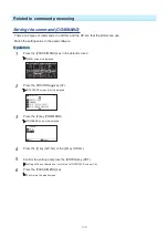
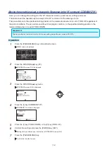
5
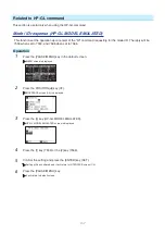
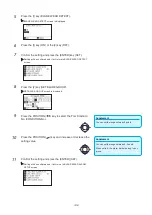
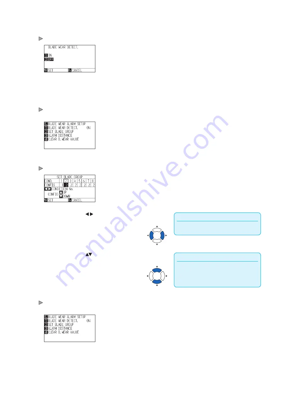
Press the [1] key (BLADE WEAR DETECT.).
BLADE WEAR DETECT. screen is displayed.
6
Press the [1] key (ON) or the [2] key (OFF).
7
Confirm the setting and press the [ENTER] key (SET).
Setting will be confirmed and it will return to BLADE WEAR DETECT.
screen.
8
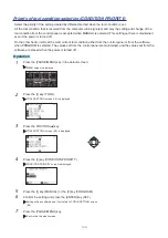
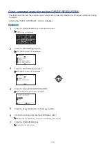
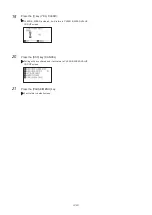
Press the [2] key (SET BLADE GROUP).
SET BLADE GROUP screen is displayed.
Supplement
You can set the range between 2 and 8.
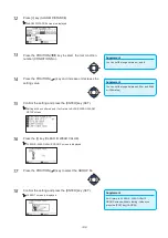
9
Press the POSITION ( ) key to select the Tool Condition
No. (CONDITION No.).
Supplement
You can set the range between 0, 2 and 8.
When set to 0, the alarm will not belong to any
group.
10
Press the POSITION ( ) key and increase or decrease the
setting value.
11
Confirm the setting and press the [ENTER] (SET).
Setting will be confirmed and it will return to BLADE WEAR ALARM
SETUP screen
Summary of Contents for CE7000-130AP
Page 1: ...USER S MANUAL MANUAL NO CE70AP UM 151 CE7000 130AP CUTTING PLOTTER...
Page 2: ......
Page 19: ...1 3 Dedicated accessories A stand with a basket is supplied...
Page 84: ......
Page 104: ......
Page 110: ......
Page 128: ......
Page 184: ......
Page 245: ...A 7 PAUSE MENU 2 Continued MENU screen AXIS SETTING 1 1 Default screen Continued 1 2...
Page 246: ...A 8 3 PAUSE MENU Continued MENU screen AREA PARAMETERS 1 1 Default screen Continued 1 2 3 4...
Page 250: ...A 12 PAUSE MENU Continued MENU screen TEST 1 2 TEST 2 2 Default screen Continued 2 3 1 1 4...
Page 251: ...A 13 PAUSE MENU MENU screen MEM SETTING 1 1 1 Default screen Continued Default screen Finish...
Page 254: ......
Page 258: ......
Page 260: ......

