background image

2-10

 3 

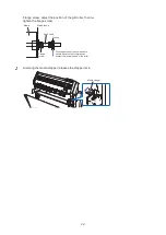
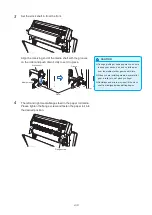
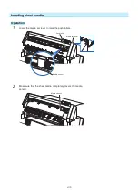
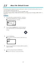
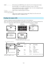
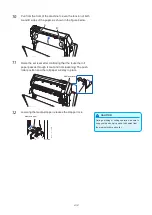
Set the stock shaft in from the front.

 CAUTION

 During a plotting or cutting operation, be sure 

to keep your hands, hair, and so forth away 
from the media stocker, gears and rollers. 

 When you are installing media, be careful for 

gear, a roller, etc. not pinch you finger.

 Deviations and errors may result if the stock 

shaft is misaligned when plotting begins.

Align the receiving end of the media shaft with the grooves 
on the roller and push down firmly to set it in place.

Stock shaft

Groove

Roller 

Media stopper 

 4 

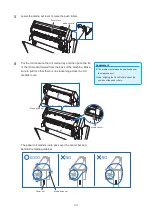
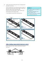
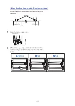
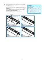
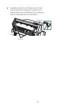
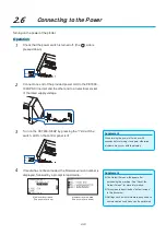
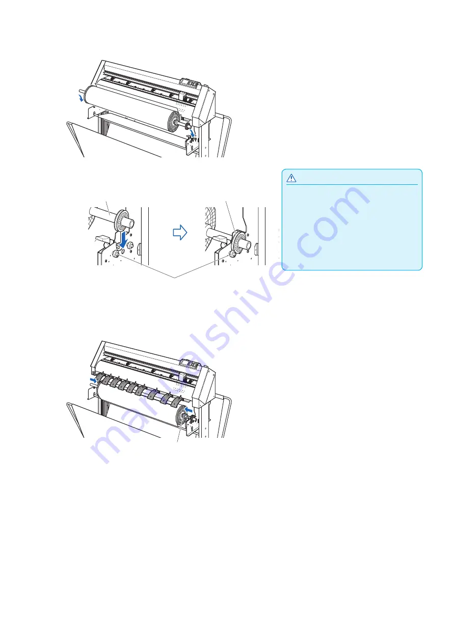
The left and right media flanges feed in the paper roll media. 
Please tighten the flange screw and fasten the paper roll into 
the desired position.

Flange screw

Summary of Contents for CE7000-130AP

Page 1: ...USER S MANUAL MANUAL NO CE70AP UM 151 CE7000 130AP CUTTING PLOTTER...

Page 2: ......

Page 3: ...orporation 2 The product specifications and other information in this manual are subject to change without notice 3 While every effort has been made to provide complete and accurate information please...

Page 4: ...he machine and using either the plotting pen or the cutter pen to cut In this instruction manual the word media refers to paper roll media sheet media or marking film Prior to use Be sure to read the...

Page 5: ...body Promptly return used blades to the cutter case provided Blade tip For the used blade put it in the supplied cutter blade case and discard them in accordance with the local regulations Cutter plun...

Page 6: ...and poor cutting results be careful not to allow hands hair clothing or other foreign objects to become entangled with the tool carriage or loaded media while the plotter is operating Machine Caution...

Page 7: ...is warped or has a larger internal diameter Please make sure to use the Paper Exposure Time and Number of Pre Feeds settings When setting AP mode The media can start to stretch or contract after it i...

Page 8: ...COMMISSION RADIO FREQUENCY INTERFERENCE STATEMENT NOTE This equipment has been tested and found to comply with the limits for a Class A digital device pursuant to part 15 of the FCC Rules These limit...

Page 9: ...n space Please secure a space for installation as according to the below illustration CAUTION Frontward and backward the machine please take enough space for operation 100 mm 500 mm 600 mm 600 mm Fron...

Page 10: ...10 A Table 2 200 V to 240 V Power Supply Voltage Range Plug Configuration Plug Type Supply Voltage Selector Settings Reference Standards Power Cable Europe 250 V 10 A 200 V CEE 7 VII IEC320 CEE13 TYPE...

Page 11: ...NG VI FEDERAL COMMUNICATIONS COMMISSION RADIO FREQUENCY INTERFERENCE STATEMENT VI USE SHIELDED CABLES VI Installation space VII Selecting a power cable VIII Chapter 1 Product Summary 1 1 Checking the...

Page 12: ...32 Selecting the TOOL CONDITION number Condition No 2 32 Setting the tool condition 2 34 Setting the tool 2 36 Setting Condition No 1 Pen plunger specific 2 36 Setting for Condition No 2 to No 8 For...

Page 13: ...e 4 8 Setting the space rear 4 9 4 2 Copy Duplicate Cutting 4 11 When media change mode is OFF 4 11 When media change mode is ON 4 14 4 3 Panel Cutting 4 16 4 4 Cross Cut Force 4 18 Chapter 5 Manual P...

Page 14: ...egarding Cutting Time 8 1 Sorting the Cutting Data 8 2 8 2 Perform Automatic Pre Feed When Cut Data is Received 8 4 8 3 Perform Automatic Pre Feed When Media is Set Initial Feed 8 6 8 4 Setting Feed S...

Page 15: ...N PRIORITY 11 3 Related to GP GL command 11 4 Setting the step size GP GL STEP SIZE 11 4 Enabling Disabling the and commands COMMAND 11 5 Moving the pen while raised or lowered in Response to the W co...

Page 16: ...Confirm the Cutting Data 13 19 13 6 Self Diagnostic Test 13 21 Reading the error message 13 23 Appendix A 1 Main Specifications A 2 A 2 Supplies A 3 Supplies A 3 A 3 External Dimensions A 4 A 4 Menu T...

Page 17: ...1 Chapter 1 Product Summary This chapter explains how to connect this machine to your computer PRODUCT SUMMARY 1 1 Checking the Accessories 1 2 Nomenclature 1 3 Assembling 1 4 Connecting to the Comput...

Page 18: ...r Blade Manual 1 of each Cutter plunger PHP33 CB09N HS 1 pc Cutter blades CB09UB 1P 1 pc Oil based ballpoint pen plunger PHP34 BALL 1 set Oil based ballpoint pen KB700 BK 1P 1 pc Cutter blade adjustme...

Page 19: ...1 3 Dedicated accessories A stand with a basket is supplied...

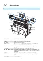
Page 20: ...sensor is used to sense the leading edge of the media The rear sensor is used to sense the trailing edge of the media Tool carriage Moves the cutter pen or plotting pen across the media during cuttin...

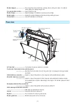
Page 21: ...Media sensors AC line inlet Inlet where the power cable is connected Push roller hold down force switching lever Switches the hold down force of the push roller to 3 stages of strong medium and weak U...

Page 22: ...1 6 1 3 Assembling For assembly of the stand refer to the stand ST0121 assembly instructions supplied with the stand...

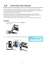
Page 23: ...se one of the USB cable standard accessories the network LAN cable commercially available product or the RS 232C cable commercially available product to connect Use the cables specified by Graphtec ma...

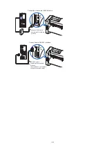
Page 24: ...network LAN interface Network LAN cable commercially available product Computer Connection via RS 232C interface Computer RS 232C cable commercially available product 9 pin female 9 pin female straig...

Page 25: ...Cutter Plunger 2 2 Attaching a Tool 2 3 Loading Media Paper 2 4 Aligning the Push Rollers 2 5 About the Default Screen 2 6 Connecting to the Power 2 7 How to Use Control Panel 2 8 Setting Feeding Meth...

Page 26: ...different plungers to suit the diameter of the cutter blade to be mounted the 0 9 mm cutter plunger is provided as a standard accessory Be sure to mount the cutter blade in the corresponding cutter pl...

Page 27: ...HP33 CB09N HS PHP33 CB15N HS Please fully insert the cutter blade straight into the plunger cap If the cutter blade cannot be inserted straight please insert the cutter blade after pressing the insert...

Page 28: ...tests If a thin media such as a film is used use the supplied magnifier to adjust it Adjust the blade length by turning the blade length adjustment knob Turn the knob in direction A to extend the bla...

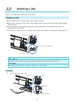
Page 29: ...ter is turned on or whenever the tool is moving The tool holder is suitable only for use with the cutter plunger Please refrain from attaching the plotting pen to it Tool holder Bracket to hold tool T...

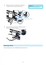
Page 30: ...pper part of the holder Flange Bracket to hold tool This tool holder is not set backward Tool holder Forward Tool holder Top view 3 Make sure that the tool bracket is engaged on the tool s flange and...

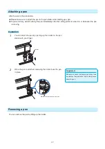
Page 31: ...whenever the pen is moving Operation 1 You can attach the pen by opening up the holder on the pen station with your finger Holder Supplement Make sure to check that the top part of any tools mounted o...

Page 32: ...e media Loading Roll Media Loading Sheet Media CAUTION Notes when using roll media If the media is not put in the basket and there are problems in the media feed reduce the media feed speed Take all c...

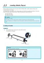
Page 33: ...en re tighten the flange screw Groove Flange screw Media flange Media Grooved portion of the components should be set so that the grooves contact the receiving end of the roller Stock shaft 2 Lowering...

Page 34: ...roller etc not pinch you finger Deviations and errors may result if the stock shaft is misaligned when plotting begins Align the receiving end of the media shaft with the grooves on the roller and pu...

Page 35: ...s about the position of the push rollers 6 Put the roll media on the roll media tray and then push the tip of the roll media forward from the back of the machine Make sure to pull it so that there is...

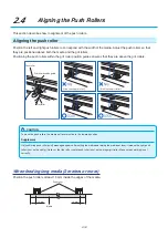
Page 36: ...sure the push rollers are on top of the grit rollers Use the grit roller position guide to make sure the push rollers are set on top of the grit rollers You can adjust the push roller s hold down forc...

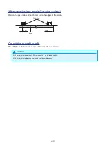
Page 37: ...e push rollers at least 5 mm inside the edges of the media Push roller Media 5 mm 5 mm 8 Raise the media stopper to lock Media stopper 9 When removing the paper please stand to the side of the main as...

Page 38: ...onfirming that the route the roll paper passes through is taut and not slackening The push roller position and the roll paper will stay in place Media set lever CAUTION During a plotting or cutting op...

Page 39: ...Loading sheet media Operation 1 Lower the media set lever to raise the push rollers Media sensor Media set lever Push roller 2 Make sure that the sheet media completely covers the media sensor Media s...

Page 40: ...roller hold down force Use the 5 push rollers to push down the sides and center of the media Use the grit roller position guide and make sure the push rollers are on top of the grit rollers You can ad...

Page 41: ...he end of the paper using the holes above and below the media guide as a reference point Raise the set lever after confirming there is no slackening to secure the sheet paper and push roller position...

Page 42: ...ller Grit roller Grit roller position guide It isn t on the grit roller It isn t on the grit roller CAUTION To move the push rollers the media set lever must be in the lowered position Supplement If a...

Page 43: ...5 mm inside the edges of the media Push roller Media 5 mm 5 mm For minimum width media The CE7000 130AP can take media of 594 mm A1 size or more CAUTION The media must be at least 125 mm in length in...

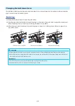
Page 44: ...own force switching lever is lower it is in Strong mode When it is upper it s in Low OFF mode Hold down force Low OFF Hold down force Medium Hold down force Strong Lever Lever Lever CAUTION Please swi...

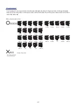
Page 45: ...the hold down force of the push rollers inside both ends to lower than both ends When using five push rollers GOOD NG When three hold down forces are different All other than above Medium Medium Mediu...

Page 46: ...pter 10 Operation 1 Once the machine is powered on with the switch a message will be displayed after the version is displayed Here LANGUAGE setting screen is displayed 2 Use the POSITION keys to selec...

Page 47: ...blems may occur with the display 3 Turn on the CE7000 130AP by pressing the side of the switch LCD on the control panel is lit Supplement The Default Screen will appear after purchasing the machine Se...

Page 48: ...de When the PAUSE MENU key is pressed during the operation the cutting plotting operation stops ORIGIN It will set the current position as an origin point On the READY screen pressing the ENTER and OR...

Page 49: ...ion are displayed on the screen when a function is allocated to the button on the control panel Button name will be displayed in reverse when the button is enabled READY screen READY MENU screen PAUSE...

Page 50: ...key or COND TEST key are pressed MENU screen CONDITION setting screen PAUSE MENU It will return to default screen when PAUSE MENU key is pressed while displaying MENU screen COND TEST It will return t...

Page 51: ...ool and media 3 AREA Set the settings for area magnification rotation reverse etc of the cutting 4 MEDIA Set the setting of the condition for the media IF Set the settings of the condition for the int...

Page 52: ...ING screens where you can change the media type and tool conditions Up to 8 CONDITION settings can be saved with different settings in numbers 1 through 8 COND TEST This will clear the CONDITION setti...

Page 53: ...hat the media stopper is unlocked and then select a media type on the MEDIA SELECT screen Media stopper Supplement When selecting 1 or 2 key Please confirm on the confirmation screen that the media st...

Page 54: ...een When setting is finished the tool carriage s location will become the initial point If the interface or command settings have not been made make these settings before sending the data If the setti...

Page 55: ...SS CUT key in READY status Cross Cut screen is displayed CAUTION Pressing 1 or 2 key activates the tool carriage Take care to ensure that you do not cut your fingers on the cutter blade 2 Press 1 key...

Page 56: ...ON number Condition No Eight settings 1 to 8 as the TOOL CONDITION can be stored Change the setting in accordance with the material 8 types to be used by switching the setting Operation Operation with...

Page 57: ...ed and it will return to CONDITION setting screen 1 3 5 Press the COND TEST key It will return to default screen Operation Operation with the ENTER key 1 Press the ENTER key in the READY status CONDIT...

Page 58: ...s must be specified FORCE SPEED ACCELERATION OFFSET CAUTION It may result to damaging the cutter blade if the blade is extended too much Make sure the blade length is set less than the thickness of th...

Page 59: ...g to confirm that there are no faint lines or other problems during plotting Supplement Finish will become coarser but the cut time is decreased when the settings for the speed and acceleration is set...

Page 60: ...ose Condition No 2 to Condition No 8 when setting up the tool conditions for the cutter plunger For more information see Selecting Tool Condition 1 Press the COND TEST key in the default screen CONDIT...

Page 61: ...the ESC key CANCEL 2 Press the 2 key TOOL TOOL setting screen is displayed 3 Press the POSITION keys and set the tool Supplement What is Offset It will adjust the difference between the tip of the bl...

Page 62: ...and increase or decrease the setting value 6 Confirm the setting and press the ENTER key SET Setting will be confirmed and it will return to CONDITION setting screen 1 3 7 Press the COND TEST key It...

Page 63: ...ess the ESC key CANCEL 2 Press the 3 key SPEED SPEED setting screen is displayed Display may vary depending on the selected tool condition number 3 Press the POSITION keys and select the tool conditio...

Page 64: ...the ESC key CANCEL 2 Press the 4 key FORCE FORCE setting screen is displayed Display may vary depending on the selected condition number 3 Press the POSITION keys and select the condition number COND...

Page 65: ...screen 2 3 is displayed Supplement It will return to CONDITION setting screen 2 3 without changing the settings when you press the ESC key CANCEL 3 Press the 1 key ACCELERATION ACCELERATION setting s...

Page 66: ...2 42 6 Confirm the setting and press the ENTER key SET Setting will be confirmed and it will return to CONDITION setting screen 2 3 7 Press the COND TEST key It will return to default screen...

Page 67: ...touch the surface of the media Media Blade Supplement Blade length can be changed by spinning the adjustor on the blade Spinning it in the A direction pushes it out while spinning it in the B directio...

Page 68: ...urrent values or do three tests with 1 values added Operation 1 Load the media for test cutting in the plotter 2 Press the COND TEST key in the default screen CONDITION setting screen 1 3 is displayed...

Page 69: ...s set correctly by following Not enough adjustment Increase the offset value Optimal offset value Too much adjustment Decrease the offset value Check the UP length when cutting When the UP length is n...

Page 70: ...6 2 12 Displaying Cutting Area Check the width of cutting area Operation 1 Press the SLOW key in the default screen The cutting area is displayed 2 Release the SLOW key I will be return to default scr...

Page 71: ...is to start from the READY status media is set as a general condition Perform the operation described in this chapter after making the plotter in READY status referring to previous chapter PRODUCT SUM...

Page 72: ...the tool pen Operation 1 Press the PAUSE MENU key MENU screen is displayed 2 Press the 1 key TOOL TOOLS SETTING 1 4 screen is displayed 3 Tool is raised or lowered every time the 1 key TOOL UP DOWN is...

Page 73: ...ep Movement Distance 1 Press the POSITION key once to move in the desired direction Tool carriage or the media will move toward the direction of the pressed POSITION key for 1 step Continuously move m...

Page 74: ...he 1 key MOVE STEP MOVE STEP screen is displayed Supplement Value chosen here will be the movement distance for the step movement 4 Press the 1 key 1 0mm or the 2 key 0 1mm Supplement It will return t...

Page 75: ...e When using Roll Media Seen from above 100 mm When using Sheet Media Seen from above To the top of the maximum cutting area Bottom of the operation area machine origin point Operation Supplement When...

Page 76: ...2 Press the 1 key No 1 the 2 key No 2 the 3 key No 3 the 4 key No 4 the key No 5 the key No 6 the key No 7 or the key No 8 while simultaneously pressing the ENTER key Setting will be confirmed and it...

Page 77: ...ocation New origin point Original origin point How to set the current position to the new origin point 1 Move the tool to the new origin point by pressing the POSITION keys when it is in READY status...

Page 78: ...e origin point will be initialized as shown below if the coordinate is rotated after moving the origin point Distance a will be maintained but distance b will be initialized New origin point Original...

Page 79: ...MENU key MENU screen is displayed 2 Press the POSITION key I F INTERFACE screen 1 4 is displayed 3 Press the 3 key HP GL ORIGIN POINT HP GL ORIGIN POINT setting screen is displayed 4 Press the 1 key...

Page 80: ...otation settings will be saved even if the power is shut off Coordinate axes rotation settings ON Coordinate axes rotation settings OFF Operation 1 Press the PAUSE MENU key MENU screen is displayed 2...

Page 81: ...out changing the settings when you press the ESC key CANCEL 5 Confirm the setting and press the ENTER key SET Setting will be confirmed and it will return to AREA PARAMETERS screen 1 1 6 Press the PAU...

Page 82: ...Pause and resume cutting Operation 1 Press the PAUSE MENU key Cutting will stop and following screen is displayed Supplement There is no effect on the selection of media type when the media set lever...

Page 83: ...operation stop screen without clearing buffer memory when ESC key CANCEL is pressed In the case that the operation is interrupted and the buffer is cleared make sure that the data transfer is stopped...

Page 84: ......

Page 85: ...hapter 4 Convenient Functions This chapter describes about the convenient functions of the plotter PRODUCT SUMMARY 4 1 Settings for Cutting 4 2 Copy Duplicate Cutting 4 3 Panel Cutting 4 4 Cross Cut F...

Page 86: ...t with HPGL command Origin point will be set at lower left of the AREA once the AREA is set It is possible to set the origin point at the center when the HP GL is selected Move the origin point to cha...

Page 87: ...the X and Y cut range for the areas on the upper right and lower left points to at least 10 mm An error message will appear for areas that are too small You will need to reset the settings for the up...

Page 88: ...et the INITIAL BLADE CONTROL POSITION of the tool setting to OUTSIDE when the setting value is set to more than 8 mm The blade might be damaged by moving the carriage outside the media under this cond...

Page 89: ...the media described below is used Use the basket Media genuine Graphtec brand products Set the speed below 30 and the acceleration below 2 Perform pre feed for the amount to be used before cutting Le...

Page 90: ...setting digits You can set the range between 20 0 and 5000 0 cm 4 Press the POSITION keys and increase or decrease the setting value Supplement It will return to MEDIA SETTING screen 1 3 without chang...

Page 91: ...if Partition Pastern is ON Operation 1 Press the PAUSE MENU key MENU screen is displayed 2 Press the 4 key MEDIA MEDIA SETTING screen 1 3 is displayed 3 Press the POSITION key MEDIA SETTING screen 3 3...

Page 92: ...cclimated to the operating environment after being pulled off the paper roll to minimize media expansion or contraction and prevent it from adversely effecting cutting or plotting After the initial fe...

Page 93: ...een 3 3 without changing the settings when you press the ESC key CANCEL 6 Confirm the setting and press the ENTER key SET Setting will be confirmed and it will return to MEDIA SETTING screen 3 3 7 Pre...

Page 94: ...r margin can be set between 7 0 mm to 30 0 mm 5 Press the POSITION keys to change the current setting Supplement It will return to MEDIA SETTING screen 3 3 without changing the settings when you press...

Page 95: ...on the data sort Turn off the data sort when you need to copy cutting with large data See Sorting the Cutting Data for data sort Watch out that it does not fall out of media when cutting with copy fun...

Page 96: ...ill be displayed If the data to be copied is larger than the cutting area Cannot copy the valid area is too small will be displayed 3 Press the COPY key COPY MODE screen is displayed 4 Press the 1 key...

Page 97: ...urned OFF Copy space can be set from 1 0 mm to 10 0 mm This setting is maintained even if the power is turned off 9 Press the 3 key COPY SPACE COPY MODE SETTINGS screen is displayed 10 Press the POSIT...

Page 98: ...e media selection will be chosen from what was selected before copying If there is no data in the buffer memory There is no data for copying in the buffer will be displayed Please send cutting data If...

Page 99: ...s the ENTER key SET The plotter starts a copy immediately Supplement Cutting data is stored even if the media is exchanged It can be copied as many times until the buffer memory is cleared It can be c...

Page 100: ...or each piece of data when a data break is caused by a command even if multiple pieces of data are sent in before the cutting finishes even when numerous pieces of Panel Cutting data are in the plotte...

Page 101: ...OW key to select the setting digits The partition length can be set from 1 0 to 2000 0 cm 7 Press the 2 key DIVIDE LENGHT DIVIDE LENGHT screen is displayed 8 Press the POSITION keys and increase or de...

Page 102: ...set the setting value to a small value if it is thick set it large Reference This setting will be saved even if the power is shut off Operation 1 Press the PAUSE MENU key MENU screen is displayed 2 Pr...

Page 103: ...e Supplement It will return to MEDIA SETTING screen 2 3 when you press the ESC key CANCEL 6 Confirm the setting and press the ENTER key SET Setting will be confirmed and it will return to MEDIA SETTIN...

Page 104: ......

Page 105: ...plain how to match up points while manually confirming the media and tool cutter pen or plotting pen points The ARMS function cannot be used for accurately matching up points PRODUCT SUMMARY 5 1 Overv...

Page 106: ...osition of each alignment mark is as shown in the following figure Alignment with 2 points 1st point or origin point 2nd point Example of axis adjustment Before and after adjustment axis adjustments a...

Page 107: ...the paper plotted already Before aligning the coordinate axes axis alignment can be performed easily by plotting the X axis line and origin position so that the origin position and coordinate axis ca...

Page 108: ...o the alignment mark position Move the tool to the position of alignment point 1 Any point on the X axis already plotted Supplement It will return to default screen without scanning when you press the...

Page 109: ...ys at the same time will move the tool carriage faster 10 Press the POSITION keys to move the tip of the tool to the alignment mark position Move the tool to the new origin point Point you want to be...

Page 110: ......

Page 111: ...tting plotter in combination with CAD for apparel PRODUCT SUMMARY 6 1 Set F Command of Cutting F_CUT 6 2 Setting a Time Out 6 3 Setting a Separator 6 4 Offline Output from USB Memory 6 5 Cross Cut Set...

Page 112: ...1 Press the PAUSE MENU key MENU screen is displayed 2 Press the 4 key MEDIA MEDIA SETTING screen 1 3 is displayed 3 Press the 1 key F COMMAND CUT F COMMAND CUT screen is displayed 4 Press the 1 key ON...

Page 113: ...eak All data up to the data break will be plotted after it cross cut will be performed Reference This setting will be saved even if the power is shut off Operation 1 Press the PAUSE MENU key MENU scre...

Page 114: ...eys and increase or decrease the setting value Supplement It will return to INTERFACE screen 4 4 without changing the settings when you press the ESC key CANCEL 6 Confirm the setting and press the ENT...

Page 115: ...it cross cut will be performed GP GL separator Set the separator at GP GL Reference This setting will be saved even if the power is shut off Operation 1 Press the PAUSE MENU key MENU screen is display...

Page 116: ...rm the setting and press the ENTER key SET Setting will be confirmed and it will return to INTERFACE screen 4 4 7 Press the PAUSE MENU key It will return to default screen HP GL separator Set the sepa...

Page 117: ...arator is not performed 5 Press the POSITION keys to change the setting Supplement It will return to INTERFACE screen 4 4 without changing the settings when you press the ESC key CANCEL 6 Confirm the...

Page 118: ...mit of the number of display characters is 25 characters More characters than 25 can be displayed by scrolling Scroll is displayed after a few moments after selecting the item The extension is xpf plt...

Page 119: ...following screen is displayed 4 Press the 1 key SELECTS DATA FILE SELECTS DATA FILE screen is displayed Supplement Press the POSITION keys to change the file 5 Press the POSITION keys to select the f...

Page 120: ...rence This setting will be saved even if the power is shut off Operation 1 Press the PAUSE MENU key MENU screen is displayed 2 Press the 4 key MEDIA MEDIA SETTING screen 1 3 is displayed 3 Press the P...

Page 121: ...creen 3 3 without changing the settings when you press the ESC key CANCEL 6 Confirm the setting and press the ENTER key SET Setting will be confirmed and it will return to MADIA screen 1 3 7 Press the...

Page 122: ...margin value set here is added to the maximum value of X plotted Feed direction of media Rear position plotted Cross Cut position Value of rear margin X Reference This setting will be saved even if th...

Page 123: ...s the SLOW key to select the setting digits 5 Press the POSITION keys to change the setting Supplement It will return to MEDIA SETTING screen 3 3 without changing the settings when you press the ESC k...

Page 124: ...d or if Panel Cutting is ON Operation 1 Press the PAUSE MENU key MENU screen is displayed 2 Press the 4 key MEDIA MEDIA SETTING screen 1 3 is displayed 3 Press the POSITION key MEDIA SETTING screen 3...

Page 125: ...creen 3 3 without changing the settings when you press the ESC key CANCEL 6 Confirm the setting and press the ENTER key SET Setting will be confirmed and it will return to MADIA screen 3 3 7 Press the...

Page 126: ...After the initial feed is complete the paper will be fed backwards to half the preset feed length and exposed for the set amount of time This function is available when the Initial Feed or if Panel C...

Page 127: ...setting Supplement It will return to MEDIA SETTING screen 3 3 without changing the settings when you press the ESC key CANCEL 6 Confirm the setting and press the ENTER key SET Setting will be confirm...

Page 128: ......

Page 129: ...ne Adjust the moving speed and force of the tool and the control method to prevent these problems This chapter describes the setting regarding the quality of the cutting PRODUCT SUMMARY 7 1 Cutting th...

Page 130: ...te smoothly Tangential mode is a control method to precisely cut corners where two straight lines meet See below With the tangential mode the blade is advanced so it will overcut at the corners before...

Page 131: ...TANGENTIAL MODE TANGENTIAL MODE screen is displayed 4 Press the POSITION keys and select the tool condition number CONDITION No 5 Press the 1 key MODE1 the 2 key MODE2 or the 3 key OFF to select the...

Page 132: ...is displayed Supplement It is enabled when Tangential Mode is set When it is set to OFF the screen below will be displayed 3 Press the 4 key OVERCUT OVERCUT screen is display 4 Press the 1 key Conditi...

Page 133: ...nge between 0 0 mm and 0 9 mm 11 Press the POSITION keys and increase or decrease the setting value 12 Confirm the setting and press the ESC key PREVIOUS Length for overcut END will be selected and it...

Page 134: ...mmediately after the lowering of the tool when tangential mode is selected enabling the cutter blade to penetrate the media rapidly As an example if the cutting force is 25 and the initial down force...

Page 135: ...n 3 3 without changing the settings when you press the ESC key CANCEL 6 Confirm the setting and press the ENTER key SET Setting will be confirmed and it will return to CONDITION setting screen 3 3 7 P...

Page 136: ...STEP PASS is the value of the STEP PASS multiplied by the distance set in the STEP SIZE Supplement This setting will be saved even if the power is shut off The cut image may not be what you intended...

Page 137: ...n 1 4 without changing the settings when you press the ESC key CANCEL 5 Confirm the setting and press the ENTER key SET Setting will be confirmed and it will return to TOOLS SETTING screen 1 4 6 Press...

Page 138: ...ol when there are angles with large angle change hence reducing the time to make the blade control But if it is set too large there will be not enough angle control of the blade and the cut result may...

Page 139: ...tting value Supplement It will return to TOOLS SETTING screen 1 4 without changing the settings when you press the ESC key CANCEL 6 Confirm the setting and press the ENTER key SET Setting will be conf...

Page 140: ...of the total distance For example a setting of 0 05 adjusts a distance of 2 m 2 000 mm by 2 000 x 0 05 1 mm making 2 001 mm Supplement This setting will be saved even if the power is shut off Operatio...

Page 141: ...8 Confirm the setting and press the ESC key PREVIOUS X DISTANCE ADJUST will be confirmed and it will return to D ADJ screen 9 Press the 3 key Y Y DISTANCE ADJUST screen is displayed Supplement You ca...

Page 142: ...1 1 without changing the settings when you press the ESC key CANCEL 12 Confirm the setting and press the ENTER key SET Setting will be confirmed and it will return to AREA PARAMETERS screen 1 1 13 Pr...

Page 143: ...ter is adjusted in UP MODE The perforation patter can be set for each condition number Supplement Use the Tool Holder forward Use Tool Holder forward when cutting with any perforation pattern aside fr...

Page 144: ...ey 2 Press the POSITION key CONDITION setting screen 3 3 is displayed 3 Press the 3 key CUT LINE PATTERN CUT LINE PATTERN screen is displayed 4 Press the 1 key Condition No CONDITION No screen is disp...

Page 145: ...ENGTH CUT LENGTH and UP LENGTH 9 Confirm the setting and press the ESC key PREVIOUS TYPE No will be selected and it will return to CUT LINE PATTERN screen Supplement You can set the range between 1 an...

Page 146: ...ts 13 If the USER is chosen in step 8 press the 3 key CUT L and the 4 key UP L to set the cut length and tool up length Follow steps 10 to 12 for this operation Supplement It will return to CONDITION...

Page 147: ...tial Blade Direction Setting outside the cutting area Selecting SPECIFIED Y POSITION will initialize Initial Blade Direction Setting at the Y direction fixed position that has been set When media narr...

Page 148: ...POSITION keys to move the tool position and then press the ENTER key to make the setting 5 Press the 1 key 2 mm BELOW the 2 key Y OUTSIDE or the 3 key SPECIFIED Y POSITION Supplement It will return to...

Page 149: ...PAUSE MENU key MENU screen is displayed 2 Press the 1 key TOOL TOOLS SETTING screen 1 4 is displayed 3 Press the 4 key OFFSET FORCE OFFSET FORCE screen is displayed 4 Press the POSITION keys to select...

Page 150: ...OOL 2 tool attached to the forward of the tool holder and TOOL 1 tool attached to the pen station you can correct it by entering the adjustment value Operation 1 Press the PAUSE MENU key MENU screen i...

Page 151: ...rm the tool position and press the ENTER key Using the pen plunger Tool 1 plot a mark Next using the cutter plunger Tool 2 plot a mark When plotting is completed TOOL OFFSET ADJ screen is displayed 7...

Page 152: ...TION keys and increase or decrease the setting value 13 Confirm the setting and press the ESC key PREVIOUS TOOL OFFSET ADJ screen is displayed 14 Repeat steps 4 to 13 until the misalignment between th...

Page 153: ...ury Supplement Cross Cut is available only when using roll media Sheet media cannot be cross cut Clean the cutting groove regularly with a cotton bud or the like If the dust or the like accumulates th...

Page 154: ...utting it manually after feeding it with the POSITION key When the FEED CROSS CUT exe is selected the roll media is cross cut after feeding 1 page When specifying 1 page set a value obtained by adding...

Page 155: ...he characteristics of the media and tools and the contents of the cutting data This chapter describes the settings affecting the cutting time In addition to this chapter there are settings affecting t...

Page 156: ...pplement Sorting will start the process after all the data are stored in the buffer memory so it takes time to start the cutting Sorting might not be effective for the data that is created efficiently...

Page 157: ...n you press the ESC key CANCEL 6 Confirm the setting and press the ENTER key SET Setting will be confirmed and it will return to TOOLS SETTING screen 2 4 Supplement mark is displayed at the right of t...

Page 158: ...Initial Feed Supplement The setting for AUTO PRE FEED when cutting data is received is maintained even if the power is turned off Setting of the AUTO PRE FEED length is not linked to the setting of t...

Page 159: ...d 50 0 m Press the SLOW key to select the setting digits 7 Press the POSITION keys and increase or decrease the setting value 8 Confirm the setting and press the ESC key PREVIOUS FEED LENGTH is select...

Page 160: ...edia Set Supplement This setting will be saved even if the power is shut off Operation 1 Press the PAUSE MENU key MENU screen is displayed 2 Press the 4 key MEDIA MEDIA SETTING screen 1 3 is displayed...

Page 161: ...rmally set to NORMAL Pre Feed of Media Paper or Marking Film Perform Automatic Pre Feed When Media is Set Initial Feed Perform Automatic Pre Feed When Cut Data is Received Supplement This setting will...

Page 162: ...o MEDIA SETTING screen 2 3 without changing the settings when you press the ESC key CANCEL 6 Confirm the setting and press the ENTER key SET Setting will be confirmed and it will return to MEDIA setti...

Page 163: ...tool when it is cutting lowered is set to slow speed for the hard to cut media hard or sticky Supplement This setting will be saved even if the power is shut off Operation 1 Press the PAUSE MENU key M...

Page 164: ...eys and increase or decrease the setting value Supplement It will return to TOOLS SETTING screen 3 4 without changing the settings when you press the ESC key CANCEL 6 Confirm the setting and press the...

Page 165: ...order it is received DISABLED If several coordinates are received continuously it will directly move to the last coordinate received Cutting time can be reduced if it is set to DISABLED if the time t...

Page 166: ...n to TOOLS SETTING screen 3 4 without changing the settings when you press the ESC key CANCEL 6 Confirm the setting and press the ENTER key SET Setting will be confirmed and it will return to TOOLS SE...

Page 167: ...sually set to the NORMAL POSITION Supplement This setting will be saved even if the power is shut off Operation 1 Press the PAUSE MENU key MENU screen is displayed 2 Press the 1 key TOOL TOOLS SETTING...

Page 168: ...ll return to TOOLS SETTING screen 3 4 without changing the settings when you press the ESC key CANCEL 6 Confirm the setting and press the ENTER key SET Setting will be confirmed and it will return to...

Page 169: ...etting Regarding Interface This chapter describes setting regarding interface PRODUCT SUMMARY 9 1 Setting Interface 9 2 Clearing the Buffer Memory 9 3 I F LAN 9 4 Connecting with RS 232C 9 5 User sele...

Page 170: ...use that some computer equipped with a USB 3 0 interface is not compatible with USB 2 0 or later interface you need to check it Do not perform the followings Do not connect or disconnect the USB cable...

Page 171: ...el The transfer condition should be set to the same in the software used and in the CE7000 130AP If there is a mistake in the settings an error may displayed in the plotter and lack of data can cause...

Page 172: ...is stopped Operation 1 Press the PAUSE MENU key MENU screen is displayed 2 Press the POSITION key I F INTERFACE screen 1 4 is displayed 3 Press the 1 key BUFFER CLEAR BUFFER CLEAR screen is displayed...

Page 173: ...address Set the subnet mask Set the gateway Display the MAC address Setting the DHCP DHCP settings depend on the configuration of network equipment and the customer s environment For details please s...

Page 174: ...CP screen is displayed 6 Press the 1 key ON or the 2 key OFF Supplement It will return to INTERFACE screen 2 4 without changing the settings when you press the ESC key CANCEL 7 Confirm the setting and...

Page 175: ...sk and gateway obtained from the DHCP server are displayed Operation 1 Press the PAUSE MENU key MENU screen is displayed 2 Press the POSITION key I F INTERFACE screen 1 4 is displayed 3 Press the POSI...

Page 176: ...SUBNET MASK SUBNET MASK setting screen is displayed Supplement Press the SLOW key to select the setting digits 9 Press the POSITION keys to set the subnet mask 10 Confirm the setting and press the ESC...

Page 177: ...press the ESC key PREVIOUS It will return to NETWORK LAN setting screen Supplement It will return to INTERFACE screen 2 4 without changing the settings when you press the ESC key CANCEL 14 Confirm the...

Page 178: ...egion For details please contact the distributor where you purchased When the RS 232C interface is not equipped the menu will not be displayed Switching the setting number you want to use Operation 1...

Page 179: ...ss the ESC key PREVIOUS It will return to RS 232C setting screen 8 Confirm the setting and press the ENTER key SET Setting will be confirmed and it will return to INTERFACE screen 2 4 9 Press the PAUS...

Page 180: ...Supplement Match it to the software you are using 6 Press the POSITION keys and increase or decrease the setting value 7 Confirm the setting and press the ESC key PREVIOUS The baud rate is selected an...

Page 181: ...ayed Supplement Match it to the software you are using It will return to RS 232C setting screen 2 3 without changing the settings when you press the ESC key PREVIOUS Enq Ack setting is available only...

Page 182: ...WER LEFT LOWER LEFT LOWER LEFT CENTER CENTER CENTER Separator PG NR J0 SP PG SP None None Time out 0 0 120 120 1 10 0 0 Page length mm 1500 3000 1500 5000 3000 1500 5000 5000 Transfer conditions 9600N...

Page 183: ...screen 4 4 is displayed 4 Press the 4 key SELECT USER SELECT USER screen is displayed Supplement You can set from setting no 1 to 8 5 Press the POSITION keys to select the setting number Supplement I...

Page 184: ......

Page 185: ...10 1 Chapter 10 Settings Regarding Operation Environment This chapter describes setting regarding the operation environment...

Page 186: ...ss the POSITION key ADV ADVANCE screen 1 4 is displayed 3 Press the 2 key LANGUAGE SELECTION LANGUAGE SELECTION screen is displayed 4 Press the POSITION keys and select the language In these instructi...

Page 187: ...splayed 2 Press the POSITION key ADV ADVANCE screen 1 4 is displayed 3 Press the 3 key LENGTH UNIT LENGTH UNIT screen is displayed 4 Press the 1 key METRIC or the 2 key INCH Supplement It will return...

Page 188: ...ED Turn it DISABLED when setting undetectable media with high transmittance When set to DISABLED the cutting mat may be damaged Please be sure to configure the area Operation 1 Press the PAUSE MENU ke...

Page 189: ...eturn to default screen Enabling Disabling the push roller sensors PUSH ROLLER SENSOR This function enables or disables the push roller sensors that detect the width of the media CAUTION Usually pleas...

Page 190: ...ress the 1 key ENABLED the 2 key INSIDE DISABLED or the 3 key DISABLED Supplement When DISABLE has been set the home sensor position is not detected so depending on the data a position error could occ...

Page 191: ...POSITION key ADV ADVANCE screen 1 4 is displayed 3 Press the POSITION key ADVANCE screen 4 4 is displayed 4 Press the 4 key FAN POWER FAN POWER screen is displayed 5 Press the 1 key NORMAL or the 2 ke...

Page 192: ...Press the POSITION key ADV ADVANCE screen 1 4 is displayed 3 Press the 4 key BEEP FOR KEY OPE BEEP FOR KEY OPE setting screen is displayed 4 Press the 1 key ON or the 2 key OFF Supplement It will retu...

Page 193: ...s the POSITION key ADVANCE screen 2 4 is displayed 4 Press the 1 key POSI KEY SPEED SLOW KEY POSI KEY screen is displayed Supplement You can set the range between 1 and 15 m s 5 Press the POSITION key...

Page 194: ...key ADVANCE screen 2 4 is displayed 4 Press the 2 key POSI KEY SPEED POSI KEY screen is displayed Supplement You can set the range between 1 and 15 m s 5 Press the POSITION keys and increase or decrea...

Page 195: ...ed 3 Press the POSITION key twice ADVANCE screen 3 4 is displayed 4 Press the 1 key PAUSE MENU KEY SETTING PAUSE MENU KEY SETTING screen is displayed 5 Press the 1 key MENU or the 2 key PAUSE Suppleme...

Page 196: ...3 4 is displayed 4 Press the 4 key LCD CONTRAST LCD CONTRAST screen is displayed Supplement You can set the range between 30 and 30 5 step 5 Press the POSITION keys and increase or decrease the settin...

Page 197: ...11 1 Chapter 11 Settings of Controls from Computer This chapter describes setting regarding the controls from the computer...

Page 198: ...the PAUSE MENU key in the default screen MENU screen is displayed 2 Press the POSITION key I F INTERFACE screen 1 4 is displayed 3 Press the 2 key COMMAND COMMAND screen is displayed 4 Press the 1 key...

Page 199: ...panel or from the software when PROGRAM is selected The values set from the control panel are maintained and the values set from the software are erased when the power is turned off Operation 1 Press...

Page 200: ...en MENU screen is displayed 2 Press the POSITION key I F INTERFACE screen 1 4 is displayed 3 Press the POSITION key INTERFACE screen 2 4 is displayed 4 Press the 1 key GP GL STEP SIZE GP GL STEP SIZE...

Page 201: ...n the default screen MENU screen is displayed 2 Press the POSITION key I F INTERFACE screen 1 4 is displayed 3 Press the POSITION key INTERFACE screen 2 4 is displayed 4 Press the 4 key COMMAND COMMAN...

Page 202: ...g position in the lowered status when it is set to TOOL DOWN Supplement This has an effect on the tool cutter only For the pen setting always the pen is raised PEN UP Operation 1 Press the PAUSE MENU...

Page 203: ...when set to 7586 Operation 1 Press the PAUSE MENU key in the default screen MENU screen is displayed 2 Press the POSITION key I F INTERFACE screen 1 4 is displayed 3 Press the 4 key HP GL MODEL EMULA...

Page 204: ...the default screen MENU screen is displayed 2 Press the POSITION key I F INTERFACE screen 1 3 is displayed 3 Press the POSITION key twice INTERFACE screen 3 4 is displayed 4 Press the 2 key CIRCLE RES...

Page 205: ...hapter describes the settings for the maintenance PRODUCT SUMMARY 12 1 Daily Maintenance 12 2 Replacing Cutter Blade 12 3 Cleaning the Cutter Pen 12 4 Cutter Plunger Exchange 12 5 Setting the Alarm fo...

Page 206: ...th water 4 Clean the plotter s paper sensors using a cloth moistened in a neutral detergent diluted with water Never use thinner benzene alcohol or similar solvents to clean the sensors cleaners such...

Page 207: ...Turn the blade length adjustment knob in the direction of the B arrow and pull the blade into the plunger One scale unit approximately 0 1 mm Scale Scale PHP33 CB09N HS PHP33 CB15N HS 2 Turn the plun...

Page 208: ...utter blade straight into the plunger cap If the cutter blade cannot be inserted straight please insert the cutter blade after pressing the insertion port of the cutter blade several times Insertion p...

Page 209: ...ild up CAUTION To avoid bodily injury handle cutter blades with care Cleaning 1 Please clean off paper dust and media powder build up from the blade After cleaning it return it to its proper place Spi...

Page 210: ...ith the media When the tip of the cutter plunger gets worn down cut quality suffers When the tip of the plunger cap gets worn down it is recommended that you exchange the cutter plunger Cutter Plunger...

Page 211: ...e should be replaced BLADE WEAR DETECT ON OFF SET BLADE GROUP ALARM DISTANCE and BLADE WEAR DETECT settings are required Operation 1 Press the PAUSE MENU key MENU screen is displayed 2 Press the 1 key...

Page 212: ...LADE GROUP SET BLADE GROUP screen is displayed Supplement You can set the range between 2 and 8 9 Press the POSITION key to select the Tool Condition No CONDITION No Supplement You can set the range b...

Page 213: ...increase or decrease the setting value 15 Confirm the setting and press the ENTER key SET Setting will be confirmed and it will return to BLADE WEAR ALARM SETUP screen 16 Press the 4 key CLEAR B WEAR...

Page 214: ...R B WEAR is cleared it will return to CLEAR B WEAR VALUE GROUP screen 20 Press the ESC key CANCEL Setting will be confirmed and it will return to CLEAR B WEAR VALUE GROUP screen 21 Press the PAUSE MEN...

Page 215: ...right It also describes the settings of the plotter confirming the cutting data and method to create test patterns PRODUCT SUMMARY 13 1 Troubleshooting 13 2 Printing the Setting of the Plotter 13 3 C...

Page 216: ...lotter is defective Check that the power cord is securely connected to the plotter s AC line inlet and the electrical outlet Check that the power is supplied to the electrical outlet Contact your Grap...

Page 217: ...ct disturbing the operation and turn on the plotter after turning it off once External force is applied to the pen carriage while cutting Move the object disturbing the operation and turn on the plott...

Page 218: ...pecified length Slight distance error Media is slipping Make the speed slower Reduce the moving speed Perform feeding Setting the Tool Condition Pre Feed of Media Paper or Marking Film Setting the Too...

Page 219: ...the blade has passed Media is rubbed by the tip of the tool plunger Adjust the blade length and the cutting FORCE settings The cutting results differ from the specified size The STEP SIZE has been set...

Page 220: ...figure to drive the plotter from the menu of the software The software configuration regarding the output device has been changed Reset the interface settings of the software The plotter s interface c...

Page 221: ...ror 2 Wrong number of parameters was specified Execute the command with the correct number of parameters E03003 Error 3 An unusable parameter was executed Execute a recognizable parameter E03005 Error...

Page 222: ...he I O related command Check the program E03014 Error 14 Too many parameters in the I O related command Check the program E03015 Error 15 Framing error parity error or overrun error has occurred Set t...

Page 223: ...13 9 ARMS Error Messages Error Displayed LCD Display Cause Solution E04001 Tilt to adjust with AXIS ALIGNMENT is too large Reload the media...

Page 224: ...01009 The plotter is defective Contact your sales representative or the Graphtec call center E01010 The plotter is defective Contact your sales representative or the Graphtec call center E01011 The pl...

Page 225: ...n function of the tool carriage and turn the power back on If the error display continues to show please contact the store where you bought the product or our Customer Center E05001 Data larger than t...

Page 226: ...sage Symptom LCD Display Description W06009 When panel cutting has been set to ON the following functions are not available ARMS function AREA function COPY function BARCODE CUT function CONTINUOUS OP...

Page 227: ...the middle Operation Supplement See Loading Media Paper or Marking Film for loading the media 1 Load a media larger than A3 size Supplement See Attaching a Tool for setting the pen tool For changing...

Page 228: ...ys CAUTION Do not place you hand around the moving areas The tool carriage will start moving so there is a chance of injury 8 Confirm that movable parts of the tool and media can safely operate and pr...

Page 229: ...per or Marking Film for loading the media 1 Load a media larger than A3 size Supplement See Attaching a Tool for setting the pen tool For changing the tool conditions please refer to Selecting Tool Co...

Page 230: ...rm that operation area of tool and media is safe Supplement It will return to TEST screen without printing by pressing the ESC key CANCEL SELF TEST 8 Press the 1 key DONE Plotting of the test pattern...

Page 231: ...or Marking Film for loading the media 1 Load a media larger than A1 size Supplement See Attaching a Tool for setting the pen tool For changing the tool conditions please refer to Selecting Tool Condit...

Page 232: ...age will start moving so there is a chance of injury 7 Confirm that operation area of tool and media is safe Supplement It will return to TEST screen without printing by pressing the ESC key CANCEL 8...

Page 233: ...or the command setting when the printed output and the display of transmission data does not match Check the transmission condition and the command Operation Supplement See Loading Media Paper or Mar...

Page 234: ...injury 7 Confirm that operation area of tool and media is safe Supplement It will return to TEST screen without printing by pressing the ESC key CANCEL DATA DUMP 8 Press the 1 key DONE 9 Send the cut...

Page 235: ...ight after the power is turned on DIAGNOSTICS cannot be selected from the menu once any operation such as loading media is performed Operation 1 Confirm that the power is turned off 2 Turn the power o...

Page 236: ...xt test will start It will return to TEST screen once all the test items are completed Test items are as following It may be changed 1 Set lever sensor 2 Home sensor 3 Push roller sensor 4 X media sen...

Page 237: ...there is no error Up to 4 error messages will be displayed on the screen Up to 32 error messages can be displayed by pressing the POSITION key When displayed while the power is on it indicates how lo...

Page 238: ...Supplement Press the POSITION key in the screen of step 4 as necessary and repeat steps 5 and 6 if there are multiple error messages you would like to see 6 Press the ENTER key CONFIRM when the error...

Page 239: ...A 1 Appendix This chapter describes the specification of the plotter PRODUCT SUMMARY A 1 Main Specifications A 2 Supplies A 3 External Dimensions A 4 Menu Tree A 5 Initial Setting...

Page 240: ...pen type Water based fiber tip and oil based ballpoint Compatible media Mono vinyl chloride media fluorescent media and reflective media up to 0 25 mm thick Excluding high intensity reflective film In...

Page 241: ...FIBER Plunger for water based fiber tip pen set of 1 Oil based ballpoint pen plunger PHP34 BALL Plunger for oil based fiber tip pen set of 1 Water based fiber tip pen KF700 BK 1 set 10 pcs Black KF700...

Page 242: ...A 4 A 3 External Dimensions H D2 W D1 Unit mm Dimensional accuracy 5mm CE7000 130AP External dimensions approx W x D1 D2 x H Unit mm 1704 1148 811 1215 Stand and basket are included...

Page 243: ...A 5 A 4 Menu Tree Continued Default screen CONDITION setting 1 3 CONDITION setting 2 3 CONDITION setting 3 3 COND TEST ENTER COPY 1 2 3 2 3 4 1 3 4...

Page 244: ...A 6 MENU screen 2 3 4 1 2 3 1 2 3 1 2 TOOLS SETTING 1 4 TOOLS SETTING 2 4 TOOLS SETTING 3 4 PAUSE MENU 1 Continued Default screen Continued TOOLS SETTING 4 4...

Page 245: ...A 7 PAUSE MENU 2 Continued MENU screen AXIS SETTING 1 1 Default screen Continued 1 2...

Page 246: ...A 8 3 PAUSE MENU Continued MENU screen AREA PARAMETERS 1 1 Default screen Continued 1 2 3 4...

Page 247: ...A 9 MEDIA SETTING 2 3 MEDIA SETTING 3 3 4 PAUSE MENU Continued MENU screen MEDIA SETTING 1 3 Default screen Continued 1 2 3 4 1 2 3 1 2 3 4...

Page 248: ...A 10 PAUSE MENU Continued MENU screen INTERFACE 1 4 Default screen Continued INTERFACE 2 4 INTERFACE 3 4 INTERFACE 4 4 2 3 1 4 2 3 1 2 1 4 2 3 1 4 When the RS 232C interface is installed...

Page 249: ...A 11 PAUSE MENU Continued MENU screen ADVANCE 1 4 ADVANCE 2 4 ADVANCE 3 4 ADVANCE 4 4 Default screen Continued 2 3 1 2 1 2 1 1 4 4 4...

Page 250: ...A 12 PAUSE MENU Continued MENU screen TEST 1 2 TEST 2 2 Default screen Continued 2 3 1 1 4...

Page 251: ...A 13 PAUSE MENU MENU screen MEM SETTING 1 1 1 Default screen Continued Default screen Finish...

Page 252: ...PAPER LOAD FUNCTION 2 PAPER READY TIME 180sec INTERFACE I F COMMAND HP GL HP GL ORIGIN POINT LOWER LEFT HP GL MODEL EMULATED 7586 GP GL STEP SIZE 0 100mm RS 232C SWITCHING SETTING NUMBERS No 1 RS232C...

Page 253: ...6 2 Same as Condition No 1 from TANGENTIAL MODE to INITIAL DOWN FORCE Same as Condition No 1 CUT LINE PATTERN 1 CONDITION 5 Condition No Condition No 5 TOOL CB09U SPEED FORCE ACCELERATION 20 8 2 Same...

Page 254: ......

Page 255: ...ace 9 2 IP address 9 7 Sign 1 2 3 4 2 25 A About the Default Screen 2 22 Accessories 1 2 AC line inlet 1 5 Adjusting the blade length 2 4 Adjustment for Cutting Out 2 45 Adjustment of Offset 2 45 Adju...

Page 256: ...n 2 7 Removing the tool 2 6 Replacing Cutter Blade 12 3 Reset 3 6 Roll media 2 8 ROTATE 3 10 RS 232C 9 10 RS 232C interface 9 3 RS 232C interface connector 1 5 S Selecting Tool Condition 2 32 Self Dia...

Page 257: ...13 15 TO ENSURE SAFE AND CORRECT USE Cutter 1 2 TOOL 2 27 Tool carriage 1 4 Tool holder 1 4 2 5 TOOL UP HEIGHT 8 13 Tool up movement 8 11 U UP MODE 7 15 USB cable 1 2 USB interface 9 2 USB interface c...

Page 258: ......

Page 259: ...Specifications are subject to change without notice CE7000 130AP User s Manual CE70AP UM 151 MAY 30 2019 1st edition 01 GRAPHTEC CORPORATION...

Page 260: ......
Reviews: