1-5
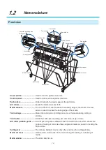
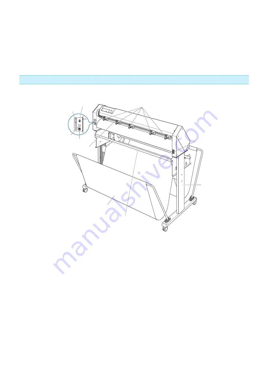
Media stopper .........................This stops the stock shaft from spinning when setting in media. It is utilized
when pulling roll media straight out.
Pen station/Pen holder ..........A second pen is set.
Media flange ...........................Fixes the paper roll (media) in place as per settings.
Media guide ............................Guides the paper (media) during the plotting/cutting process.
Stock shaft ..............................A shaft that takes in roll media.
Rear view
AC line inlet
Basket
Push roller hold-down force
switching lever
Media guide bar
Stand
Network (LAN) interface
connector
USB interface
connector
RS-232C interface
connector
USB memory dedicated
connector
Media sensors
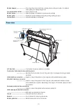
AC line inlet ............................. Inlet where the power cable is connected.
Push roller hold-down force switching lever
.........................Switches the hold-down force of the push roller to 3 stages of strong, medium
and weak.
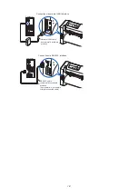
USB interface connector .......Used to connect the plotter to the computer with a USB interface cable.
RS-232C interface connector
.........................Used to connect the plotter to the computer with a RS-232C interface cable.
(It is available as an option depending on the region. For details, please contact
your dealer.)
Network (LAN) Interface connector
.........................Used to connect this plotter with a network (LAN) I/F.
USB memory dedicated connector
................................................USB memory dedicated connector.
Stand .......................................A stand to put the machine on.
Basket ......................................The container for receiving the media.
Media guide bar ......................Shaft that used to set the roll media.
Summary of Contents for CE7000-130AP
Page 1: ...USER S MANUAL MANUAL NO CE70AP UM 151 CE7000 130AP CUTTING PLOTTER...
Page 2: ......
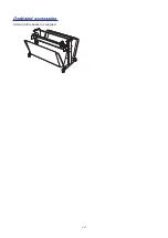
Page 19: ...1 3 Dedicated accessories A stand with a basket is supplied...
Page 84: ......
Page 104: ......
Page 110: ......
Page 128: ......
Page 184: ......
Page 245: ...A 7 PAUSE MENU 2 Continued MENU screen AXIS SETTING 1 1 Default screen Continued 1 2...
Page 246: ...A 8 3 PAUSE MENU Continued MENU screen AREA PARAMETERS 1 1 Default screen Continued 1 2 3 4...
Page 250: ...A 12 PAUSE MENU Continued MENU screen TEST 1 2 TEST 2 2 Default screen Continued 2 3 1 1 4...
Page 251: ...A 13 PAUSE MENU MENU screen MEM SETTING 1 1 1 Default screen Continued Default screen Finish...
Page 254: ......
Page 258: ......
Page 260: ......

