5-18
10
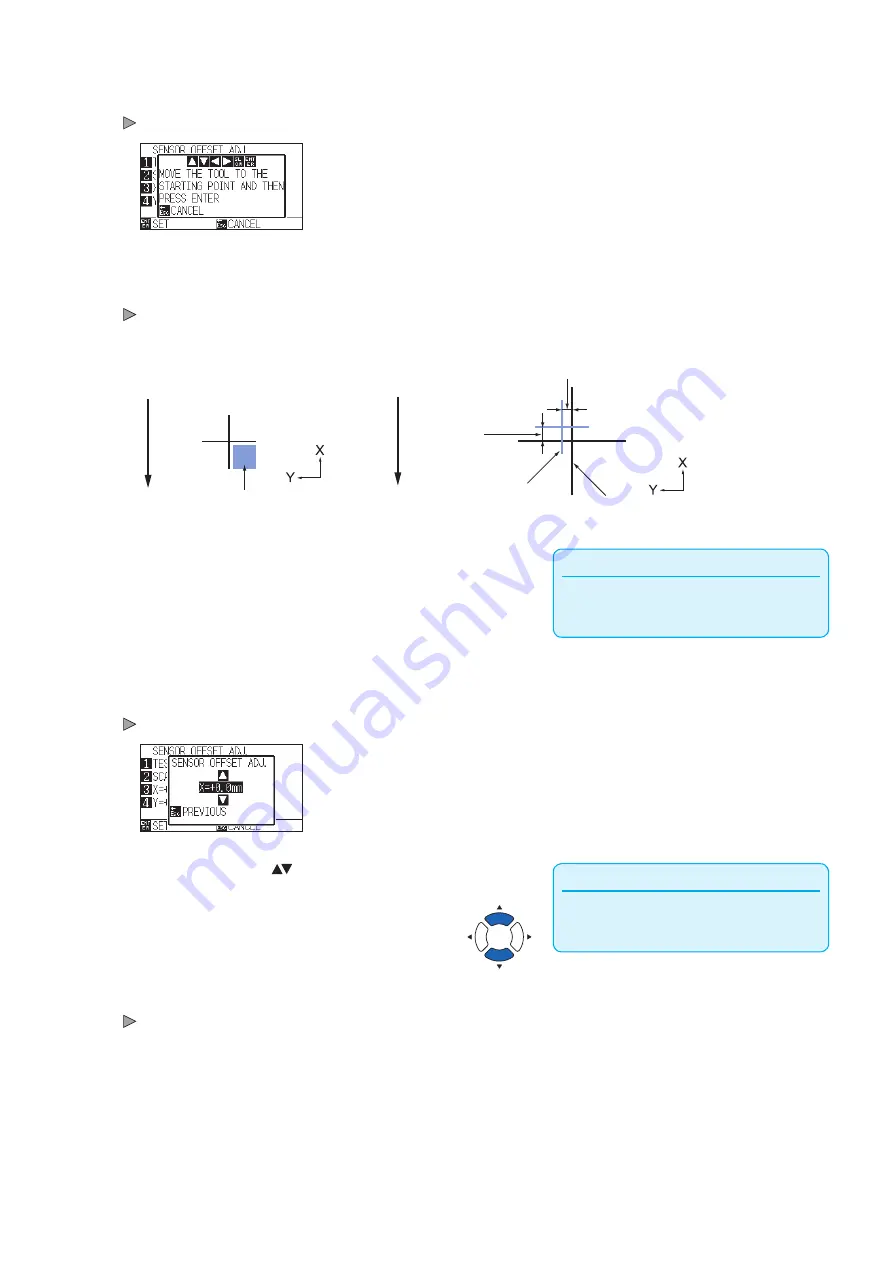
Press [2] key (SCAN). The following message is displayed.
Following message is displayed.
11
Confirm that the tool is at the position shown in the left image
(grey square area), and press the [ENTER] key.
It will scan the registration mark, and then plot the registration mark for
comparison. It will return to SENSOR OFFSET ADJ. screen once the
plotting is completed.
Fe
ed d
ire
ct
io
n o
f m
ed
ia
Distance adjustment value Y
Distance
adjustment
value X
Registration mark for
adjustment
Registration mark for
comparison
Fe
ed d
ire
ct
io
n o
f m
ed
ia
Align the tool to this area
Supplement
Position of the registration mark is measured at
the center of the line.
12
Using the registration mark plotted in step 9, measure the
distance of how much the adjustment registration mark
needs to be moved so both will overlap, and record the
value. As an example, in the figure above, it needs to move
in negative directions for both X and Y directions, so both of
the adjustment values will be negative values.
13
Press the [3] key (X).
SENSOR OFFSET ADJ. X screen is displayed.
Supplement
You can set the range between -3.0mm and
+3.0mm.
14
Press the POSITION ( ) keys and increase or decrease the
setting value. Set the X value measured in step 12.
15
Confirm the setting and press the [ESC] key (PREVIOUS).
SENSOR OFFSET ADJ.will be confirmed and it will return to SENSOR
OFFSET ADJ. screen.
Summary of Contents for CE7000 Series
Page 1: ...CE7000 SERIES CUTTING PLOTTER USER S MANUAL MANUAL NO CE7000 UM 151 ...
Page 2: ......
Page 18: ......
Page 104: ......
Page 118: ......
Page 168: ......
Page 220: ......
Page 232: ......
Page 254: ......
Page 290: ......
Page 328: ......
Page 343: ...A 15 PAUSE MENU Continued MENU screen TEST 1 2 TEST 2 2 Default screen Continued 2 3 1 1 4 ...
Page 348: ......
Page 352: ......
Page 354: ......


