7-23
Supplement
•
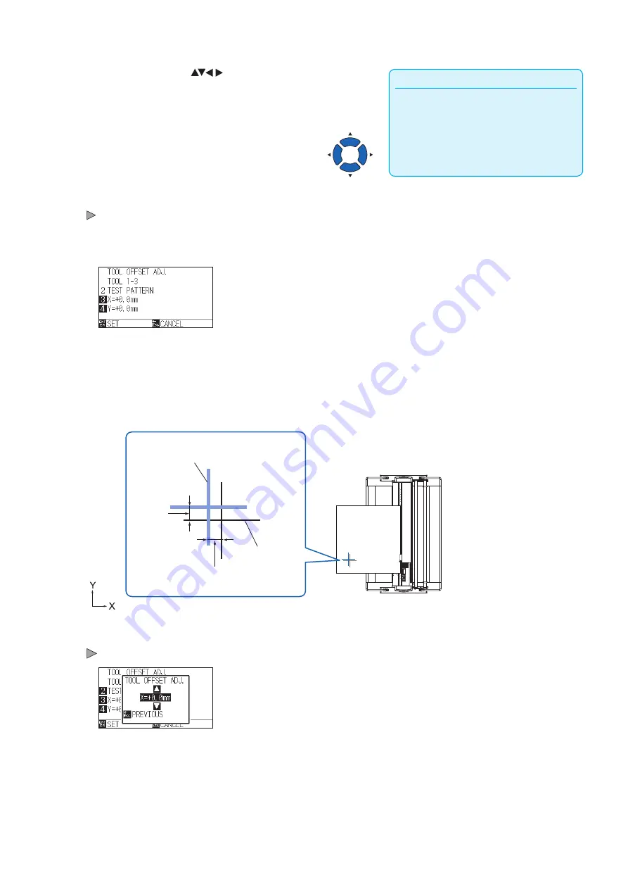
It will return to TOOL OFFSET ADJ. screen
without changing the settings when you press
the [ESC] key (CANCEL).
•
Pressing the POSITION and [SLOW] keys at
the same time moves the tool carriage slowly.
5
Press the POSITION (
) keys to move the tool carriage
to the position where the test pattern is plotted.
Move it inside of a cutting area greater than 50 mm on both
the X and Y axes.
6
Confirm the tool position and press the [ENTER] key.
Using the pen plunger (Tool 1), plot a "+" mark.
Next, using the pen plunger (Tool 3), plot a "+" mark.
When plotting is completed, TOOL OFFSET ADJ. screen is displayed.
7
Using "+" plotted with the pen plunger (Tool 1) as a reference,
measure how much the "+" cut by the cutter plunger (Tool 3)
deviates. (For example, in the case shown in the figure, it is
deviated in the -X direction / + Y direction, so enter X = + *
mm, Y = - * mm.)
X mm
Y mm
"+" plotted with
the cutter plunger
(Tool 1)
"+" plotted with
the cutter plunger
(Tool 3)
8
Press the [3] key (X=+0.0mm).
Tool 1-3 Interval Adjustment (X) screen is displayed.
Summary of Contents for CE7000 Series
Page 1: ...CE7000 SERIES CUTTING PLOTTER USER S MANUAL MANUAL NO CE7000 UM 151 ...
Page 2: ......
Page 18: ......
Page 104: ......
Page 118: ......
Page 168: ......
Page 220: ......
Page 232: ......
Page 254: ......
Page 290: ......
Page 328: ......
Page 343: ...A 15 PAUSE MENU Continued MENU screen TEST 1 2 TEST 2 2 Default screen Continued 2 3 1 1 4 ...
Page 348: ......
Page 352: ......
Page 354: ......


