6-3
Chapter 6 Troubleshooting
6.2
Confirming
Error Messages
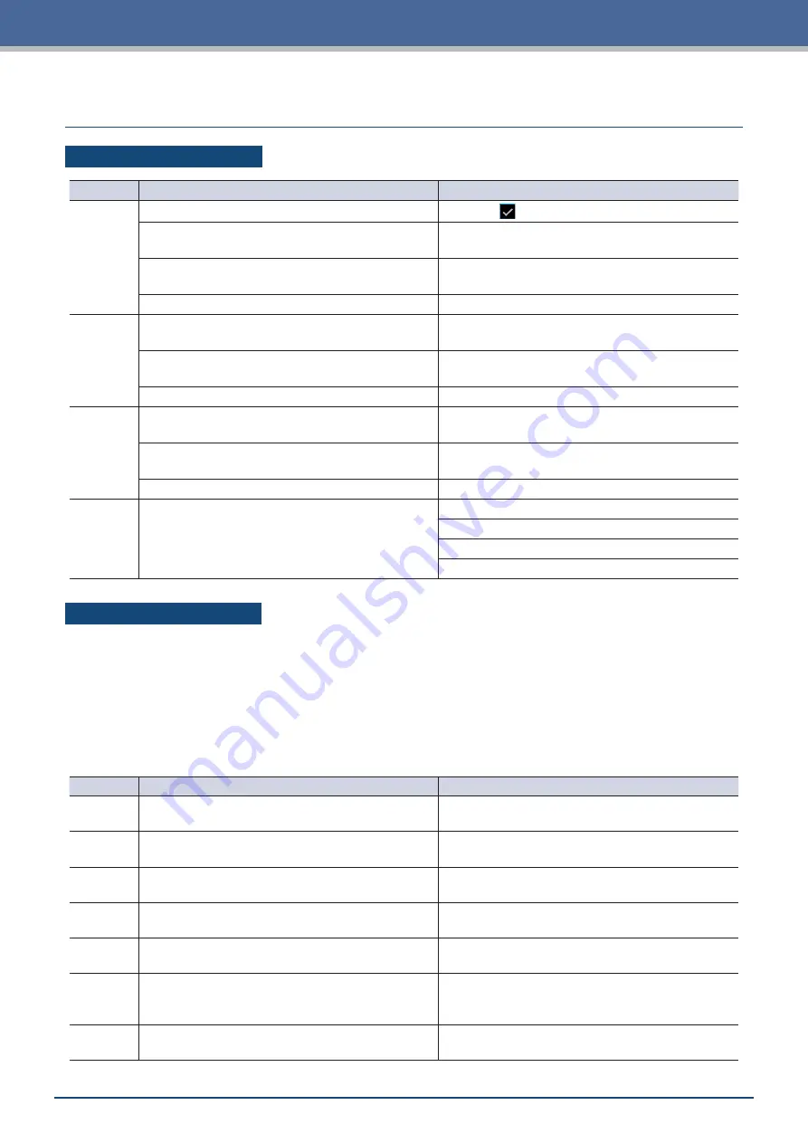
GP-GL Command Errors
Error No.
Displayed
Solution
E02001
An order that cannot be recognized was forwarded.
Touch the
(Confirm).
Noise was input when the computer was turned ON. In the menu of the software, perform settings for
operating the device.
The setting for the device the software will output to
has changed.
Fix the setting of the software interface.
The settings on the plotter's interface have changed.
Fix the settings on the plotter's interface.
E02004
A numerical parameter of a command has exceeded
the acceptable range.
In the menu of the software, perform settings for
operating the device.
The setting for the device the software will output to
has changed.
Fix the setting of the software interface.
The settings on the plotter's interface have changed.
Fix the settings on the plotter's interface.
E02005
An error related to receipt of data has occurred within
the interface.
In the menu of the software, perform settings for
operating the device.
The setting for the device the software will output to
has changed.
Fix the setting of the software interface.
The settings on the plotter's interface have changed.
Fix the settings on the plotter's interface.
E02006 Data that exceeds the cutting area has been
received.
Confirm the data.
Confirm the size and cutting area of the media.
Confirm the settings for the scale.
Confirm the settings for the size of steps.
HP-GL Command Errors
When an HP-GL command error is displayed, the cause of such in most cases is one of the two reasons listed
below.
•
The setting for the model the application software will output to has changed.
•
The settings on the interface of the device have changed.
If one of these reasons has caused the error, take the measures listed below to resolve the problem.
•
Fix the setting for the model the application software will output to.
•
Fix the settings on the interface of the device.
Error No.
Displayed
Solution
E03001
Error 1
An order that cannot be recognized was executed.
Execute a command that can be used.
E03002
Error 2
The value of a parameter was incorrectly specified.
Execute the command with a proper value for the
parameter.
E03003
Error 3
A parameter that cannot be used was executed.
Execute a parameter that can be used.
E03005
Error 5
A character set that cannot be used was specified.
Specify a character set that can be used.
E03006
Error 6
The coordinates of a command have been specified
outside of the cutting area.
Execute the command with coordinates within the
cutting area.
E03007
Error 7
An overflow of the buffer memory has occurred while
processing the downloadable character buffer or
polygon buffer, etc.
Adjust the buffer size.
E03010
Error 10
While executing an output order, another output order
was executed.
Check the program.
Summary of Contents for CELITE-50
Page 1: ...USER S MANUAL CE LITE 50 UM 151...
Page 2: ......
Page 10: ......
Page 22: ......
Page 78: ......
Page 101: ...5 23 Chapter 5 Detailed Settings 3 Select ON or OFF for WIDTH DETECTION...
Page 112: ......
Page 116: ...A 4 Appendix A 3 Appearance Drawing 164 784 227 173 400 Units mm Dimension error 5 mm...
Page 118: ...A 6 Appendix 3 PIECES Previous Page HOME SELECT FILE...
Page 119: ...A 7 Appendix TOOL ARMS MODE 1 MODE 2 MODE 3 CHECK MARK SCAN SENSOR OFFSET ADJ Next Page MENU...
Page 120: ...A 8 Appendix INTERFACE ADVANCE TEST Previous Page AREA MEDIA MENU...
Page 127: ......
Page 128: ......


