2-4
Chapter 2 Basic Operations
2.2
Setting the Media Set Levers
Set the media set levers to the locked position, except the following conditions.
Moving the push roller position or removing jammed media.
When this device will not be used for a long period, set the media set levers to the released position.
The "SET THE MEDIA SETTING LEVER." is displayed when the media set levers did not set to the locked
position when the HOME menu is selected.
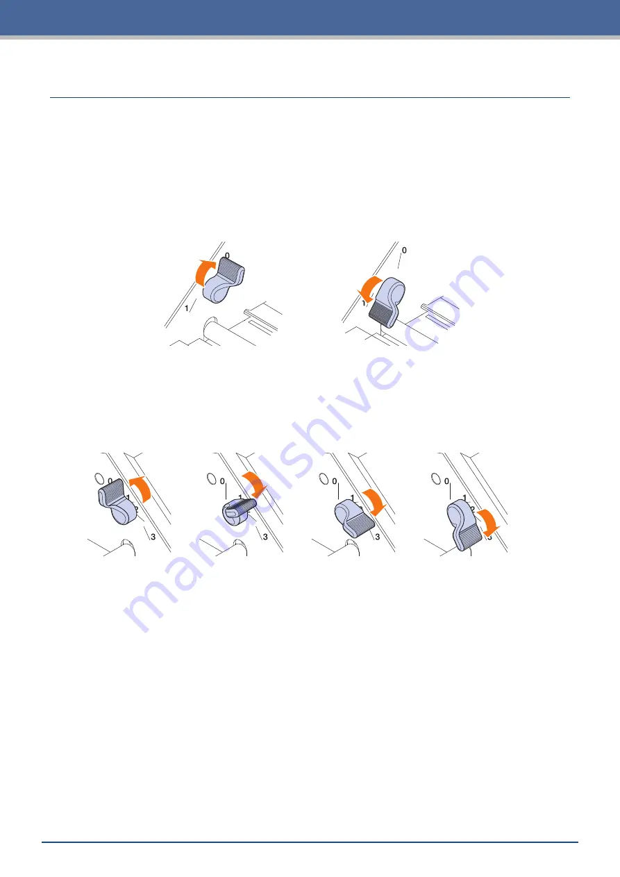
Setting the Media Set Lever - Left
Set the media set lever - left to the lock position to hold the media with the left side push roller.
Release
Lock
Setting the Media Set Lever - Right
There are three lock positions for the media set lever - right.
The lock position depends on the width of media.
Set the media set lever - right to the correct position.
Refer to the "1.5 Media Size and Cutting Area" to set the right side Media Set Lever to correct position.
Release
Lock 1
Lock 2
Lock 3
When the media lock lever was set to incorrect position, the message of correct position will be displayed.
Set the
media set lever - right to the correct position according with the message
Media Width and Lock Position
Lock 1: A4 / 8.5” / 220mm / B4 / 11” / A3
Lock 2: 12” / 320mm / A3+ / CARRIER SHEET / B3 / 15” / A2
Lock 3: 17” / 500mm / 20”.
Summary of Contents for CELITE-50
Page 1: ...USER S MANUAL CE LITE 50 UM 151...
Page 2: ......
Page 10: ......
Page 22: ......
Page 78: ......
Page 101: ...5 23 Chapter 5 Detailed Settings 3 Select ON or OFF for WIDTH DETECTION...
Page 112: ......
Page 116: ...A 4 Appendix A 3 Appearance Drawing 164 784 227 173 400 Units mm Dimension error 5 mm...
Page 118: ...A 6 Appendix 3 PIECES Previous Page HOME SELECT FILE...
Page 119: ...A 7 Appendix TOOL ARMS MODE 1 MODE 2 MODE 3 CHECK MARK SCAN SENSOR OFFSET ADJ Next Page MENU...
Page 120: ...A 8 Appendix INTERFACE ADVANCE TEST Previous Page AREA MEDIA MENU...
Page 127: ......
Page 128: ......


