1-4
Chapter 1 Notes Before Use
1.3
Operation Panel
Types of Screens and Operations
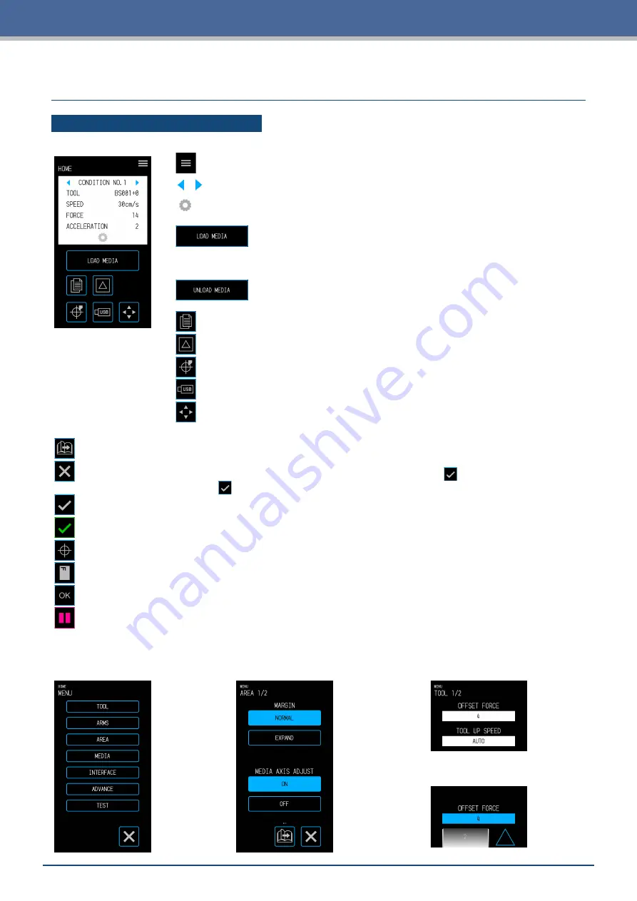
HOME Screen and Functions of Buttons
"MENU" button:
Used to transition to the "MENU" screen.
"CONDITION NO. Selection" buttons:
Used to select the CONDITION NO.
"CONDITION" button:
Used to transition to the CONDITION (cutting condition)
setting screen.
"LOAD MEDIA" button:
Used to transition to the Load Media screen.
The following screen is displayed when media is set.
"UNLOAD MEDIA" button:
Used to Unload Media that has been set.
"COPY" button:
Used to transition to the copy mode.
"CUT TEST" button:
Used to transition to the cut test screen.
"HOME" button:
Used to move the tool carriage to the home point.
"USB" button:
Used to transition to the menu for cutting from a USB memory.
Position key:
Used to transition to the position key screen.
Other Buttons
"Page" button:
Used to transition to the next page on the same tier level.
"Exit" button:
Used to exit the current screen. When touched before the (Confirm) in a screen
where the
(Confirm) is displayed, the screen is exited without setting the item.
"
Confirm" button:
Used to confirm settings.
"Execute" button:
Used to execute settings.
"Origin" button:
Used to configure the plot origin.
"Cutting Area" button:
Used to display th cutting area of the media that has been loaded.
"OK" button:
Used to confirm the position of the tool moved with the position keys.
"Stop" button:
Stops the cutting operation.
Menu Selection Screen
This screen is used to select setting
items. Please touch the button to set.
Different Button Colors
Light blue indicates the selected setting.
Please touch the button to set
.
Different Display Boxes
White boxes can be touched to
transition to the input screen.
Light blue boxes display the
current setting value.
Summary of Contents for CELITE-50
Page 1: ...USER S MANUAL CE LITE 50 UM 151...
Page 2: ......
Page 10: ......
Page 22: ......
Page 78: ......
Page 101: ...5 23 Chapter 5 Detailed Settings 3 Select ON or OFF for WIDTH DETECTION...
Page 112: ......
Page 116: ...A 4 Appendix A 3 Appearance Drawing 164 784 227 173 400 Units mm Dimension error 5 mm...
Page 118: ...A 6 Appendix 3 PIECES Previous Page HOME SELECT FILE...
Page 119: ...A 7 Appendix TOOL ARMS MODE 1 MODE 2 MODE 3 CHECK MARK SCAN SENSOR OFFSET ADJ Next Page MENU...
Page 120: ...A 8 Appendix INTERFACE ADVANCE TEST Previous Page AREA MEDIA MENU...
Page 127: ......
Page 128: ......


