background image

4-11

4 DISASSEMBLY AMD REASSEMBLY

CC100-UM-251-9370

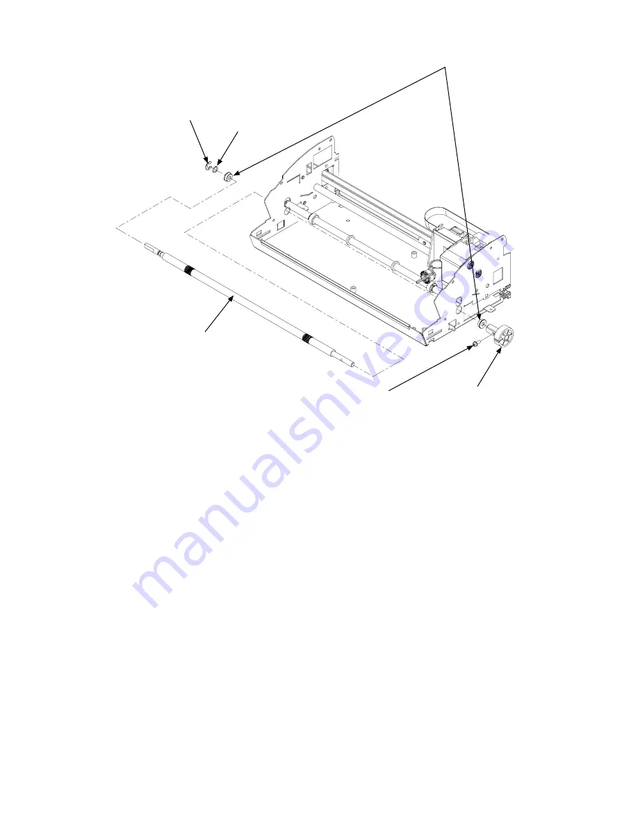
(7)  Remove the two M3L8 TP head screws holding the Y motor, and then detach the Y motor.

Collar

M3L6 pan head screw

Bearing

Feed roller

X feed roller gear

E-ring

(8)  Remove the M3L6 pan head screw holding the X feed roller gear, and then detach the X feed roller gear.

(9)  Detach the E-ring from the left side of the feed roller.

(10)  Detach the two bearings and the collar from the feed roller, and then detach the feed roller from the main unit.

Reassembly

(1)  To attach the feed roller, perform the above “Disassembly” procedure in reverse.

Summary of Contents for Craft ROBO CC100-20

Page 1: ...Craft ROBO SERVICE MANUAL MANUAL NO CC100 UM 251 CC100 20 CC100 UM 251 02 9370 ...

Page 2: ......

Page 3: ...i CC100 UM 251 9370 HISTORY OF REVISIONS No Date issued Description of revision Page Edition 1 04 08 11 First printing All 01 2 04 11 25 CC100 20 ALR Wishblade parts added 2 1 6 1 6 4 02 ...

Page 4: ...o Replace the Pinch Roller Shaft Assembly 4 7 4 8 How to Replace the Y Motor 4 8 4 9 How to Replace the X Motor 4 9 4 10 How to Replace the Feed Roller 4 10 4 11 How to Replace the Main Board 4 12 4 12 How to Replace the Y Belt 4 14 4 13 How to Replace the Carriage Unit 4 15 4 14 How to Replace the Y Flexible Cable 4 16 4 15 How to Replace the Solenoid 4 18 4 16 How to Replace the Auto Registratio...

Page 5: ... Adjusting the Auto Registration Mark Sensor Sensitivity 5 8 5 7 Adjusting the Offset of the Auto Registration Mark Sensor 5 9 5 8 Adjusting the Distance Accuracy 5 10 6 PARTS LIST 6 1 6 1 Main Unit Parts 6 1 6 2 Carriage 6 3 6 3 Other 6 4 7 BLOCK DIAGRAM 7 1 ...

Page 6: ...r pen and drives it in the vertical direction Standby switch Used to set media in place and to start or stop the main unit Feed knob Drives media back and forth USB interface connector Used to connect the USB cable AC adapter jack Used to connect the cable for the AC adapter Cutting mat Cutting or plotting work is performed on it Push roller Pushes down on the media to hold it in place Media rolle...

Page 7: ...ommon part for X and Y 8 692124120 Flexible Cable for Auto Registration Mark Sensor 1 FPC304502 9 692124112 Y Flexible Cable 1 FPC304501B 10 796212005 Y Home Sensor Assembly 1 D3C 2220 11 621242001 Feed Roller Shaft 1 621240410 Feed Roller Shaft Letter 1 For USA model 12 621242030 X Feed Gear 1 13 621243051 Y Belt 1 460TN15 7 0W 14 621243200 Y Drive Gear Pulley 1 15 621243221 Y Idler Pulley 1 16 5...

Page 8: ...orce adjustment Blade and blade holder optionset exe Electrical adjustment program Colex gauge 150 g 300 g PC USB I F cable 3 Distance adjustment Blade and blade holder optionset exe Electrical adjustment program Glass scale 300 mm PC USB I F cable 4 Auto Registration adjust ment Blade and blade holder optionset exe Electrical adjustment program PC USB I F cable ...

Page 9: ...and then detach the feed knob Feed knob Left side cover Top cover M3L8 self tapping screw Hook 2 Remove the two M3L8 self tapping screws holding the left side cover 3 Release the bottom two hooks of the left side cover and then detach the left side cover Hook Hook hole Release the hook here Reassembly 1 To attach the left side cover perform the above Disassembly procedure in reverse ...

Page 10: ...bly 1 Detach the left side cover see Section 4 1 2 Pull out the top cover from the right side cover to detach the top cover Feed knob Left side cover Top cover Right side cover M3L8 self tapping screw Hook Reassembly 1 To attach the top cover perform the above Disassembly procedure in reverse ...

Page 11: ... after you have removed the screws there is a flexible cable inside the cover Feed knob Left side cover Top cover Right side cover M3L8 self tapping screw M3L8 self tapping screw Hook 2 Release the bottom two hooks of the right side cover and then detach the right side cover Hook Hook hole Release the hook here Reassembly 1 To attach the right side cover perform the above Disassembly procedure in r...

Page 12: ...p cover see Section 4 2 3 Detach the right side cover see Section 4 3 4 Remove the two M3L6 pan head screws holding the front guide and then detach the front guide Front guide M3L6 pan head screw Note Do not scratch the main frame when you are detaching the front guide Reassembly 1 To attach the front guide perform the above Disassembly procedure in reverse ...

Page 13: ... cover see Section 4 1 2 Detach the top cover see Section 4 2 3 Detach the right side cover see Section 4 3 4 Remove the three M3L6 pan head screws holding the rear guide and then detach the rear guide Rear guide M3L6 pan head screw Reassembly 1 To attach the rear guide perform the above Disassembly procedure in reverse ...

Page 14: ...e two M3L8 pan head screws holding the ball point pen plunger holder with the limiter bracket and then detach the ball point pen plunger holder and the limiter bracket M3L8 pan head screw Feed guide M3L6 pan head screw Limiter bracket Ball point pen plunger holder 5 Remove the M3L6 pan head screw holding the feed guide and then detach the feed guide Reassembly 1 To attach the feed guide perform th...

Page 15: ... cover see Section 4 3 4 Detach the two pressure springs from the pressure bracket Pressure spring Pressure bracket 5 Lift up both sides of the pressure bracket slide the pressure shaft assembly to the left side and then detach the pressure shaft assembly from the right side Pressure shaft assembly Pressure bracket Reassembly 1 To attach the pinch roller shaft assembly perform the above Disassembl...

Page 16: ...n 4 3 4 Detach the two pressure springs from the pressure bracket see Section 4 7 5 Detach the rear guide see Section 4 5 6 Disconnect the Y motor cable which is connected to J5 on the main board 7 Remove the two M3L6 TP head screws holding the Y motor and then detach the Y motor Y motor M3L6 TP head screw M3L6 TP head screw X motor Reassembly 1 To attach the Y motor perform the above Disassembly ...

Page 17: ...n 4 3 4 Detach the two pressure springs from the pressure bracket see Section 4 7 5 Detach the rear guide see Section 4 5 6 Disconnect the X motor cable which is connected to J4 on the main board 7 Remove the two M3L6 TP head screws holding the X motor and then detach the X motor Y motor M3L6 TP head screw M3L6 TP head screw X motor Reassembly 1 To attach the X motor perform the above Disassembly ...

Page 18: ...two pressure springs from the pressure bracket see Section 4 7 5 Detach the front guide see Section 4 4 6 Detach the Y motor see Section 4 8 7 Remove the M3L6 flat head screw and the M3L6 pan head screw holding the motor bracket and then detach the motor bracket M3L6 TP head screw Y motor M3L6 flat head screw Motor bracket Feed roller Feed roller gear M3L6 pan head screw 6 Disconnect the X motor cab...

Page 19: ...feed roller gear E ring 8 Remove the M3L6 pan head screw holding the X feed roller gear and then detach the X feed roller gear 9 Detach the E ring from the left side of the feed roller 10 Detach the two bearings and the collar from the feed roller and then detach the feed roller from the main unit Reassembly 1 To attach the feed roller perform the above Disassembly procedure in reverse ...

Page 20: ...e Section 4 3 4 Detach the front guide see Section 4 4 5 Detach the rear guide see Section 4 5 6 Remove the two M3L6 pan head screws holding the guide rail and then detach the guide rail M3L6 pan head screw Flexible cable clamp Guide rail 7 Detach the three flexible cable clamps from the guide rail and then detach the Y flexible cable from the guide rail 8 Disconnect all the cables from the main boa...

Page 21: ...crews holding the main board M3L6 pan head screw Main board Main board Locking card spacer Release here 10 Release the two locking card spacers holding the main board and then detach the main board Reassembly 1 To attach the main board perform the above Disassembly procedure in reverse ...

Page 22: ...racket Y drive gear pulley Adjusting spring Y idler pulley Y left idler shaft Y tension bracket Y right idler shaft Y drive collar Y idler flange Washer Y belt Y belt clamp 7 Detach the Y tension bracket 8 Detach the Y motor see Section 4 8 9 Detach the motor bracket see Section 4 10 10 Pull out the Y right idler shaft from the Y drive pulley and then detach the Y drive pulley 11 Detach the Y left ...

Page 23: ...ings from the Y tension bracket see Section 4 12 8 Detach the Y motor see Section 4 8 9 Detach the motor bracket see Section 4 10 10 Detach the Y drive pulley see Section 4 12 11 Detach the two pressure springs from the pressure bracket see Section 4 7 12 Remove the two M3L8 pan head screws holding the left and right pressure brackets and then detach both the pressure brackets Carriage unit Left p...

Page 24: ...ection 4 5 5 Detach the guide rail see Section 4 11 6 Detach the Y flexible cable from the guide rail see Section 4 11 7 Lift up the bottom of the carriage cover and then detach the carriage cover from the carriage Carriage unit Lift up here to detach the carriage cover Carriage cover 8 Disconnect the Y flexible cable from J201 on the carriage board J201 Y flexible cable 9 Disconnect the Y flexible ca...

Page 25: ... attach the Y flexible cable perform the above Disassembly procedure in reverse Note Do not lock the clamp when you are installing the Y flexible cable to the clamp shown in the figure below If you do so the flexible cable may be damaged by the clamp Do not lock this clamp ...

Page 26: ...Section 4 3 4 Detach the guide rail see Section 4 11 5 Detach the carriage cover from the carriage see Section 4 14 6 Disconnect the solenoid cable from the carriage board 7 Remove the two pan head screws holding the solenoid and then detach the solenoid Carriage cover Solenoid Link shaft Link spring M3L8 pan head screw Carriage Reassembly 1 To attach the solenoid perform the above Disassembly pro...

Page 27: ...ail see Section 4 11 5 Detach the carriage cover from the carriage see Section 4 14 6 Detach the solenoid see Section 4 15 7 Release the hook holding the auto registration mark sensor board and then detach the auto registration mark sensor board from the carriage Auto registration mark sensor board Carriage Auto registration mark sensor board Release this hook Reassembly 1 To attach the auto regis...

Page 28: ...ow to update the system firmware 1 Copy the three upgrade software files to the same directory in the PC 2 Connect the computer and the CC100 20 via the USB interface 3 Connect the power cable to turn on the power 4 Turn on the standby switch of the CC100 20 5 Execute VerupEnglish exe 6 The following menu is displayed Confirm the note shown in the menu 7 Click the Next button to display the following...

Page 29: ... to close the VerupEnglish exe program 14 Turn off the power disconnect the power cable from the CC100 20 Note Do not use the computer for any other purpose while you are upgrading the firmware If you fail to upgrade the firmware perform the following procedure 1 Connect the power cable to the CC100 20 while pressing the standby switch for more than 5 seconds 2 Confirm that the standby LED is blinkin...

Page 30: ...ose the setup parameters for each adjustment Set up the adjustment values to the main board after you clear the Non Volatile RAM How to clear the Non Volatile RAM 1 Set the DIP switch to the NOV RAM clear mode as shown below Set bits 1 2 and 3 to ON ON 1 6 2 Connect the power cable to turn on the power 3 The Standby LED blinks when the NOV RAM clear operation is complete 4 Turn off the power disco...

Page 31: ...e two software files to the same directory in the PC 2 Connect the computer and the CC100 20 via the USB interface 3 Connect the power cable to turn on the power 4 Turn on the standby switch of the CC100 20 5 Execute Optionset exe 6 The following menu is displayed Used for the pen force adjustment Used for the auto registration mark sensor position adjustment Used for the auto registration mark sen...

Page 32: ... switch while adjusting the CC100 20 perform the following procedure 1 Click the Cancel button to exit the adjustment software 2 Connect the power cable to the CC100 20 3 Turn on the standby switch of the CC100 20 4 Execute OptionSetEnglish exe again Note 2 The OptionSetEnglish exe software will not start if the standby switch is off or the power is off The OptionSetEnglish exe software displays t...

Page 33: ...e correct force gently lift the pen up by hand lower the pen and then measure the actual force after you click the force button 9 If the measured value is not within the specification range 65 g to 70 g change the value at the right side of the Force 1 down up button so that it is 65 g to 70 g for the actual force 10 Click the Force 1 down up button again to apply the input value 11 Use the 100 g f...

Page 34: ... after you click the force button 21 If the measured value is not within the specification range 175 g to 180 g change the value at the right side of the Force 3 down up button so that it is 175 g to 180 g for the actual force 22 Click the Force 3 down up button again to apply the input value 23 Use the 300 g force gauge to measure the changed force to confirm it 24 Click the Force 3 down up button ...

Page 35: ...y switch of the CC100 20 5 Execute Optionset exe 6 Use the Pen Position buttons to move the auto registration mark sensor position to a white area on the paper Make sure there are no dirty areas or any printing directly under the sensor 7 Click the Adjust button to adjust the white level of the sensor 8 The following menu will appear when the white level adjustment is complete 9 Confirm the value s...

Page 36: ...lue blade adjustment cap 5 Turn on the standby switch of the CC100 20 6 Execute Optionset exe 7 Use the Pen Position buttons to move the cutter pen to the printed cross mark area Move the pen into this area Printed target mark Media feed direction 7 Click the Scan button to scan the printed cross mark The plotter then cuts a cross mark based on the reading of the printed cross mark 8 Confirm the of...

Page 37: ...de and the blue blade adjustment cap 5 Turn on the standby switch of the CC100 20 6 Execute Optionset exe 7 Click the Plot button to cut the test pattern X 200 mm Y 150 mm 8 Measure the X axis and Y axis distances 9 Input the values to the input boxes shown below The formula of the input value is as follows Input value for X axis 200mm measured distance x 10 For example If you measured 200 2 mm fo...

Page 38: ...cket 1 19 621243250 Adjusting Spring 2 20 621242060 Collar 2 21 621242130 Pressure Spring 30 2 22 621242050 Left Pressure Bracket 1 23 621242090 Bearing PSB 2 24 621240112 Ball point Pen Plunger Holder 1 25 E ring D5 1 26 621242021 X Collar 1 27 621242010 Bearing RFS 2 28 621240004 Main Frame Assembly 1 29 621240130 Edge Guard 1 30 621240190 Frame Edge 1 31 621243060 Locking Card Spacer 2 32 62124...

Page 39: ...6 2 6 PARTS LIST CC100 UM 251 9370 Main Unit Parts 1 2 3 4 5 6 7 44 8 9 10 11 12 45 13 14 15 16 17 18 19 20 22 21 23 24 25 26 27 28 29 30 31 32 33 34 42 27 23 21 35 20 36 37 38 39 40 41 37 43 47 ...

Page 40: ...n 1 5 621240064 Rear Guide 1 6 621243042 Lock Lever 1 7 692124120 Auto registration Sensor Flexible Cable 1 FPC304502 8 796212004 Auto registration Sensor Board Assembly 1 9 692124112 Y Flexible Cable 1 10 772124520 Relay Board 1 11 621243004 Carriage 1 12 621243030 Carriage Cover 1 13 621243070 Flexible Cable Clamp 1 14 621240090 Cushion 1 Carriage 2 1 8 6 5 7 9 10 11 12 3 4 13 14 ...

Page 41: ...er YC 1048GRC1247P 1 BS 240V 500051951 AC adapter SA45 3129 1 Japanese 100V 4 621249200 User Guide CD CC100 CDM02M 1 Use for only Graphtec model 5 621249110 Setup Manual 1 English 621249130 Setup Manual Wishblade 1 Wishblade 621249120 Setup Manual WGI 1 WGI 6 621249060 Beginners Manual 1 English 621249080 Beginners Manual Wishblade 1 Wishblade 621249120 Beginners Manual WGI 1 7 500052043 USB Cable...

Page 42: ...USB Interface AC ADAPTER SA45 3129 AC CABLE AC100 240V 50 60Hz X Motor PM42S 096 Y Motor PM42S 096 FPC304501 PR304502 FPC304502 Main Board PR304501 J202 J301 J2 J1 J7 J5 J4 J8 J9 CA304501 Y HOME SENSOR D3C 2220 REGISTRATION MARK SENSOR PR304503 J201 J203 SOLENOID SDC 0829FT ...

Reviews: