background image

3-10

CHAPTER 3. CRAFT ROBO CONTROLLER

PREFACE

PREFACE

CH 1. PRIOR TO USE

CH 1. PRIOR TO USE

CH 3. CRAFT ROBO CONTROLLER

CH 3. CRAFT ROBO CONTROLLER

INDEX

INDEX

CONTENTS

CONTENTS

CH 2. CONNECTION AND PREPARATION 

CH 2. CONNECTION AND PREPARATION 

Appendix A. Standard Specifications

Appendix A. Standard Specifications

<Other>
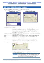
• Thick Media: Select this parameter when using Kent paper (inkjet, laser or similar paper).

• Thin Media: Select this parameter when using standard paper.

• Pen:

Select this parameter when a ballpoint pen has been mounted in the
Craft ROBO. The ballpoint pen is primarily used for test plotting
before cutting.

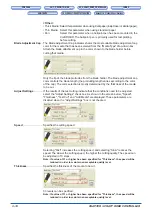
Blade Adjustment Cap .. The Blade Adjustment Cap indicator shows the most suitable blade adjustment cap

color for the media that has been selected from the "Media Type" drop-down box.
Attach the blade attachment cap in the color shown to the blade holder before
cutting that media.

Only the tip of the blade protrudes from the blade holder. The blade adjustment cap
color controls the blade length (the protruding length varies according to the color
of the cap). The color selection is mostly determined by the thickness of the media
to be cut.

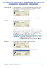
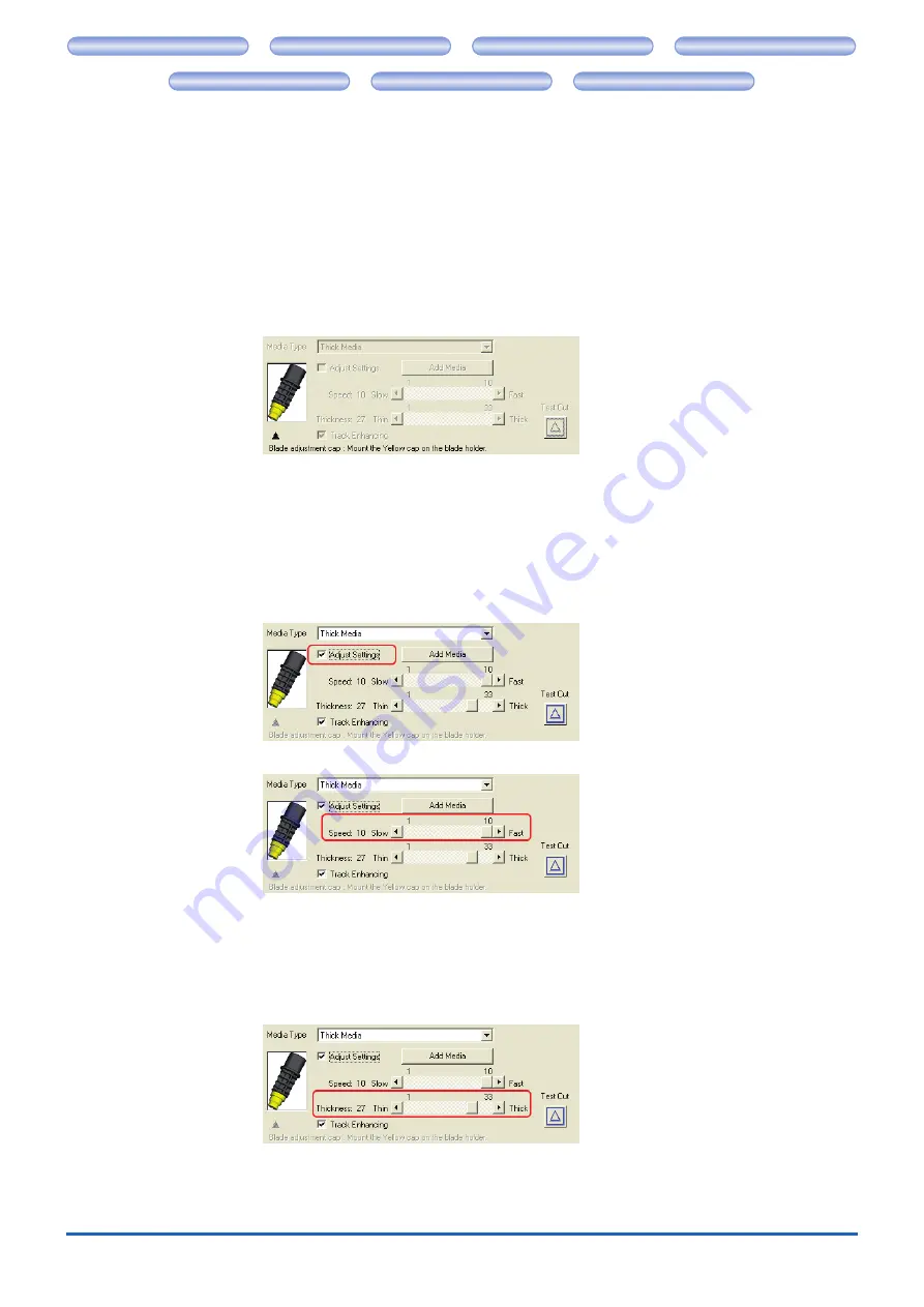
Adjust Settings ............. If the results of the test cutting indicate that the conditions need to be adjusted,

select the "Adjust Settings" check box. As shown in the screen below, "Speed",
"Thickness", "Test Cut" and "Add Media" are displayed. These parameters are
disabled when the "Adjust Settings" box is not checked.

Speed ............................ Specifies the cutting speed.

Selecting "Fast" increases the cutting speed, and selecting "Slow" reduces the
speed. The slower the cutting speed, the higher the cutting quality. The speed can
be adjusted in 10 steps.

Note: If a value of 31 or higher has been specified for "Thickness", the speed will be

reduced in order to maintain an acceptable quality level.

Thickness ...................... Specifies the thickness of the media to be cut.

33 levels can be specified.

Note: If a value of 31 or higher has been specified for "Thickness", the speed will be

reduced in order to maintain an acceptable quality level.

Summary of Contents for Craft ROBO CC200

Page 1: ... CRAFT ROBO CONTROLLER CH 3 CRAFT ROBO CONTROLLER INDEX INDEX CONTENTS CONTENTS CH 2 CONNECTION AND PREPARATION CH 2 CONNECTION AND PREPARATION Appendix A Standard Specifications Appendix A Standard Specifications USER S MANUAL MANUAL NO CC200m UM 152 CC200 ...

Page 2: ...ions may cause harmful interference to radio communications However there is no guarantee that interference will not occur in a particular installation If this equipment does cause harmful interference to radio or television reception which can be determined by turning the equipment off and on the user is encouraged to try to correct interference by one or more of the following measures Reorient o...

Page 3: ...ier sheet 2 7 Allowable cutting area of the carrier sheet 2 9 2 5 Adjusting and Mounting the Blade Holder 2 10 Blade holder construction 2 10 Blade adjustment caps and media selection 2 10 Changing the blade adjustment cap 2 11 Mounting the blade holder 2 12 2 6 Mounting a ballpoint pen 2 13 Acceptable ballpoint pens 2 13 Mounting the ballpoint pen 2 14 2 7 What to Do if This Happens 2 15 CHAPTER ...

Page 4: ...nents are included with your product If any item is missing please contact your place of purchase AC adapter Power cable 1 set USB cable 1 Quick Start Instructions 1 Craft ROBO Software CD ROM 1 Carrier sheet 1 Blade holder with blade adjustment caps 1 set Quick Application Guide 1 Ballpoint pen holder 1 Blade adjustment caps blue yellow and red Media Trial Kit 1 Note One of the blade adjustment c...

Page 5: ...g mat Cutting head Drives the blade holder pen holder to the left or right Clamp bracket Holds the blade holder pen holder and drives it up or down Standby switch Turns the power supply to the Craft ROBO on and off When the power supply is on the switch s lamp lights blue Feed knob Used to manually feed the media back and forth USB interface connector Used for connecting the USB cable AC adapter j...

Page 6: ...t ROBO to connect the AC adapter jack on the Craft ROBO to an AC outlet of the rated voltage and then turn on the power CHECKPOINT Always connect the AC adapter to the AC adapter jack before connecting the power cable to the AC outlet 1 Connect the power cable included with the AC adapter to the AC adapter 2 Plug the AC adapter cable into the AC adapter jack of the Craft ROBO 3 Plug the other end ...

Page 7: ...ided with the Craft ROBO to connect the Craft ROBO to a computer CHECKPOINT The software for the Craft ROBO must be installed before the Craft ROBO is connected to a computer See Chapter 3 3 Installing the Craft ROBO Controller Do not connect the USB cable until instructed to do by an on screen prompt The USB cable has different plug shapes on the computer side and the Craft ROBO side Always check...

Page 8: ...eet However if the sheet is loaded so that its top edge touches and is parallel to both the pinch rollers it will be straight To ensure that the loaded sheet is straight align the left edge of the sheet with the guideline indented on the front guide Place the top edge of the sheet against both pinch rollers Guideline indented on the front guide If you are using media that is not A4 size please fol...

Page 9: ...he sheet until its top edge is aligned with the rear edge of the cutting mat or with the indented guideline located next to the cutting mat Feed knob Cutting mat Guideline located next to the cutting mat If the top edge of the sheet curls up and catches on the Craft ROBO turn the feed knob in the direction toward the rear of the Craft ROBO to align the top edge of the sheet with the indented guide...

Page 10: ...and then select the desired mode in Margin Settings on the Basic Settings tab The default setting is Standard mode Align the left and right edges with the vertical guidelines making sure that the sheet is straight Allowable cutting area Allowable cutting area Media 190mm 200mm Standard mode Expanded mode 5mm 20mm Allowable cutting area Allowable cutting area 10mm 10mm 5mm 5mm 5mm 20mm If the media...

Page 11: ...m Expanded mode The width of the allowable cutting area is 200 mm If registration marks are used the allowable width is 190 mm CHECKPOINT To change the mode from Standard to Expanded or vice versa click Properties in the Print window and then select the desired mode in Margin Settings on the Basic Settings tab The default setting is Standard mode Align the left and right edges with the vertical gu...

Page 12: ...to replace it with a new carrier sheet after cutting 10 sheets Pulling on the carrier sheet to remove it from the Craft ROBO may shorten its lifetime or cause misaligned cutting Be sure to use the feed knob to remove the media If you use the Eject Media function the media will automatically be ejected to the front of the Craft ROBO after the cutting operation has been completed For further details...

Page 13: ...a that is wider than 210 mm with the carrier sheet 1 Peel off the inside liner and the liner strips on both sides of the carrier sheet so that the entire adhesive surface is visible Liner Peel off the inside liner and the liner strips on both sides of the carrier sheet 2 Press the media onto the adhesive surface of the carrier sheet CHECKPOINT When pressing the media onto the adhesive surface be c...

Page 14: ... A Standard Specifications Allowable cutting area of the carrier sheet The allowable cutting area of the carrier sheet is shown in the diagram below When using media smaller than A4 size always affix the media within the allowable cutting area In addition make sure that the edges of the media are parallel to the edges of the carrier sheet CHECKPOINT Do not use media smaller than postcard size 100 ...

Page 15: ...to which a cap containing a blade is attached The length of the blade protruding from the cap can be adjusted by selecting one of the three available blade adjustment caps Select the blade adjustment cap best suited for the media you plan to use Holder Blade adjustment cap Blue Thin film Yellow Thick film thin paper Red Thick paper such as a postcard Blade Blade adjustment caps and media selection...

Page 16: ...crew on type 1 Turn the cap in the counterclockwise direction to remove it 2 Replace it with the correct blade adjustment cap 3 Turn the cap in the clockwise direction to tighten it Holder Loosen Tighten Blade adjustment cap Assuming that the media thickness is t as shown in the figure below the blade length l should be equal to or slightly greater than t Make sure that r r r r r is never greater ...

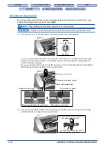
Page 17: ...t Lock lever Loosen Tighten If you are using media that does not require the carrier sheet mount the blade holder while making sure that the protrusion on the holder faces the front and that it is aligned with the notch in the clamp bracket If you are using the carrier sheet turn the protrusion on the holder 90 degrees to the right so that it fits against the protrusion on the clamp bracket Protru...

Page 18: ...ons Appendix A Standard Specifications 2 6 Mounting a ballpoint pen Acceptable ballpoint pens The ballpoint pen holder accepts the following pen types 1 Cylindrical ballpoint pens Up to 8 5 mm in diameter 2 Hexagonal ballpoint pens Up to 7 5 mm side to side 3 The tips of both pen types must extend between 3 and 3 5 mm past the ballpoint pen holder s opening Hexagonal ballpoint pen Cylindrical ball...

Page 19: ...e notched part of the clamp bracket 1 Loosen the thumbscrew on the ballpoint pen holder by turning it counterclockwise 2 Insert the ballpoint pen into the holder 3 Confirm that the tip of the ballpoint pen protrudes 3 3 5 mm from the holder 4 Tighten the thumbscrew by turning it clockwise 5 Turn the lock lever to the left OPEN direction to loosen the clamp bracket 6 Mount the ballpoint pen holder ...

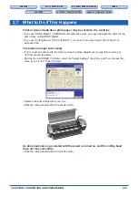
Page 20: ...ste the object at the same place on the ROBO Master If you use Cutting Master 2 for Craft ROBO you can set how many times cut at Passes on Advanced Tab The blade no longer cuts cleanly If dirt or dust has adhered to the blade remove the blade adjustment cap and then remove any dirt from around the blade Start up the Craft ROBO Controller select the Adjust Settings check box and then increase the v...

Page 21: ...such as selection of the Media Type and Craft ROBO operations such as test cutting CHECKPOINT The term media as used in this manual refers to paper film and other materials to be cut or printed on 3 1 System Requirements The minimum system requirements to run the software are as follows OS Windows 2000 Windows XP or Windows Vista CPU Pentium III 600 MHz or better Memory 128 MB minimum 256 MB recom...

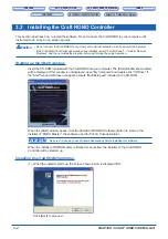
Page 22: ...ve Programs and then uninstall the program before performing the setup operation Starting up the Start window Insert the CD ROM included with the Craft ROBO into your computer The Start window shown below will be displayed If this window is not displayed open My Computer and double click CD Drive If the Start window still does not appear execute MultiSetup exe included in the CD ROM When the Start...

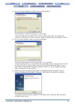
Page 23: ...ge the default folder click Next to proceed 3 Next a Select Program Folder screen will be displayed Select the program folder in which the program icon is to be placed To place the program icon in a new folder enter a new folder name in Program Folder To add the program icon to an existing folder select one from the list of Existing Folders A new folder named Craft ROBO is prepared by default If t...

Page 24: ... two ways 1 Starting up from the Windows Start menu The Craft ROBO Controller can be started up from the Windows Start menu To start it up select Start All Programs Craft ROBO Craft ROBO Controller 2 Starting up from Craft ROBO compatible software such as ROBO Master a Click Craft ROBO in the File menu of ROBO Master b The Output to Craft ROBO window will open Click OK to start up the Craft ROBO C...

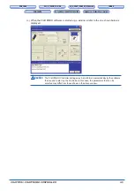
Page 25: ...CTION AND PREPARATION Appendix A Standard Specifications Appendix A Standard Specifications c When the Craft ROBO software is started up a window similar to the one shown below is displayed Caution The Craft ROBO Controller settings may be performed automatically by the software that is used to start up the Controller In this case the parameters that can be selected may differ from those shown in ...

Page 26: ...er settings See Blade Adjustment Cap Adjust Settings and Test Cut in Section 3 5 Craft ROBO Controller Settings 6 Set the Design Orientation by referring to the illustration of the plotter in the upper right corner If the Controller is started up from ROBO Master the Design Orientation is set automatically See Design Orientation in Section 3 5 7 Load media in the Craft ROBO 8 If required change th...

Page 27: ... 5 Craft ROBO Controller Settings The Search Marks function Two steps are required to read the registration marks a The Craft ROBO searches for the first registration mark which will become the reference registration mark and makes it the origin point The first registration mark is the registration mark at the bottom left of the design It is shown as a green square in the illustration of the plott...

Page 28: ... Craft ROBO Controller Settings Performing a test cut and creating a Media Type setting When creating a Media Type setting the appropriate cutting conditions must be found by adjusting the media settings and performing a test cut 1 Turn on the power to the Craft ROBO and check that the Standby switch lamp is lit blue 2 Start up the Craft ROBO Controller from the Windows Start menu See Section 3 3 ...

Page 29: ... by step instructions for easy Craft ROBO setup and operation Animated Instructions Click to display animated instructions describing the operation of the Craft ROBO and the Craft ROBO Controller About Click to display the version information of the Craft ROBO Controller currently in use Help Click to display Quick Help descriptions of the various Craft ROBO functions Cancel Click to exit the Craf...

Page 30: ...lade protrudes from the blade holder The blade adjustment cap color controls the blade length the protruding length varies according to the color of the cap The color selection is mostly determined by the thickness of the media to be cut Adjust Settings If the results of the test cutting indicate that the conditions need to be adjusted select the Adjust Settings check box As shown in the screen be...

Page 31: ... the Blade Position buttons to move the blade to the position at which test cutting is to be performed and then click the Test Cut button A 1cm x 1 cm test pattern will be cut The cutting conditions are appropriate when the results of test cutting indicate that the media is cut cleanly with faint traces of the blade on the backing material liner or carrier sheet If cutting has not been performed c...

Page 32: ...en ballpoint pen to the desired origin point using the Blade Position buttons click the Set Origin button to specify the current position as the origin This function cannot be used is not required when registration marks are used for positioning Landscape orientation Portrait orientation If the origin point has not been specified and Landscape has been selected for the media orientation the origin...

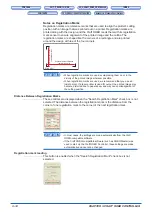
Page 33: ...arks CHECKPOINT If the Craft ROBO compatible software such as ROBO Master was used to start up the Craft ROBO Controller this parameter is automatically selected and cannot be changed Search Registration Marks Search Marks is a function that automatically searches for registration marks within a fixed range from the current position of the blade pen toward the center of the media CHECKPOINT This p...

Page 34: ...s Vertical distance between registration marks CHECKPOINT When registration marks are used avoid placing them on or in the vicinity of the printed image wherever possible When registration marks are used we recommend that you use an inkjet printer If a laser printer is used for output the printed image may become distorted due to paper skew and may cause misalignment of the cutting position Distan...

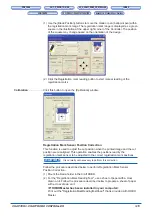
Page 35: ...of the registration marks Calibration Click this button to open the Calibration window Registration Mark Sensor Position Correction This function is used to adjust the cut position when the printed image and the cut position are misaligned This operation enables the positions read by the registration mark sensor to be adjusted to the correct registration mark positions CHECKPOINT It is normally no...

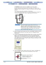
Page 36: ...is mounted in the Craft ROBO Depending on the type of media that is being used the registration mark may not be read correctly Wherever possible use a sheet of the actual media paper vinyl film that you plan to use 3 From the Media Type drop down box of the Craft ROBO Controller select the parameter that corresponds to the media used in the Registration Mark Reading Test 4 Load the RegistrationMar...

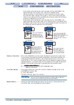
Page 37: ...ive side in the horizontal x directions and toward the positive side in the vertical y directions Horizontal x Vertical y If the cross is located at this position move it toward the positive side in the horizontal x directions and toward the negative side in the vertical y directions Horizontal x Vertical y If the cross is located at this position move it toward the negative side in both the horiz...

Page 38: ... and install it The GITKUSBP DLL functions could not be found and so the Craft ROBO Controller could not be started Please reboot your computer or re install the Craft ROBO Controller Follow the instructions in the message To install the software again first uninstall the Craft ROBO Controller currently installed If the problem is not solved download the latest version of the Craft ROBO Controller...

Page 39: ...ain If the problem is still not resolved consult the manufacturer of the application software that you are using The distances between the registration marks have not been specified correctly Please check the Distance between Registration Marks setting in your application program Make the setting once again If the problem is still not resolved consult the manufacturer of the application software t...

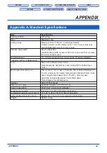
Page 40: ...d Operating speed 10 100 mm per second in 10 mm steps 10 levels selectable Loadable number of blades pens 1 Tools Blade with dedicated blade holder General purpose ballpoint pen used only with the ballpoint pen holder Media types that can be cut Film media 0 1 mm or less in thickness liner included thickness of 0 3 mm or less but excluding high intensity reflective sheets Kent paper inkjet or lase...

Page 41: ...and Turning on the Power 2 1 Connecting to a Computer 2 2 Copyright i Craft ROBO Controller Installing 3 2 Operations 3 6 Settings 3 9 Starting 3 4 System Requirements 3 1 Craft ROBO Software CD ROM 1 1 Creating a Media Type setting 3 8 Cut 3 9 Cutting head 1 2 Cutting mat 1 2 Cutting your design 3 6 D Design Orientation 3 13 Distance Between Registration Marks 3 14 Distance Correction 3 17 E Erro...

Page 42: ... Specifications Appendix A Standard Specifications Registration mark reading 3 14 Registration Mark Sensor Position Correction 3 15 Registration Marks 3 13 3 14 S Search Registration Marks 3 13 Set Origin 3 12 Standard Specifications A 1 Standby switch 1 2 Start window 3 2 T Test Cut 3 11 Test Plotting 3 7 Thickness 3 10 Track Enhancing 3 11 U USB cable 1 1 USB interface connector 1 2 W Warning i ...

Page 43: ...ER INDEX INDEX CONTENTS CONTENTS CH 2 CONNECTION AND PREPARATION CH 2 CONNECTION AND PREPARATION Appendix A Standard Specifications Appendix A Standard Specifications The specifications etc in this manual are subject to change without notice CC200m UM 152 Feburary 13 2007 1st edition GRAPHTEC CORPORATION ...

Page 44: ...X CONTENTS CONTENTS CH 2 CONNECTION AND PREPARATION CH 2 CONNECTION AND PREPARATION Appendix A Standard Specifications Appendix A Standard Specifications 503 10 Shinano cho Totsuka ku Yokohama 244 8503 Japan Tel 81 045 825 6250 Fax 81 045 825 6396 Email info graphteccorp com Web www graphteccorp com Printed in Japan ...

Reviews: