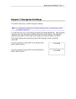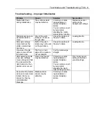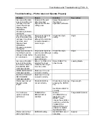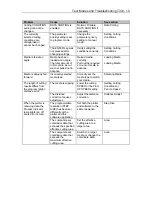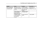
Background Settings
♦
C5 - 9
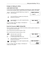
LENGTH UNIT
METRIC
\
\
INCH
CONDITION PRIORITY
MANUAL
\
\
PROGRAM
INITIAL BLADE
CONTROL POSITION
2mm BELOW
\
\
OUTSIDE
INITIAL BLADE
CONTROL POSITION
2mm BELOW
\
\
OUTSIDE
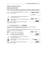
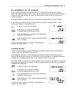
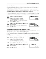
Condition Priority
This function determines the priority of programmed cutting conditions and manual settings of
cutting conditions at the plotter’s control panel.
When MANUAL is selected, commands specifying cutting conditions from the computer are
ignored and the cutting conditions can only be set at the control panel. The registered conditions
are retained in the plotter’s internal memory even while the plotter is turned off.
When PROGRAM is selected, the cutting conditions can be set either at the plotter’s control panel
or by command input from the computer. When the plotter is turned off, however, the registered
conditions are not retained.
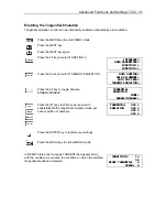
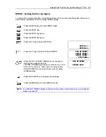
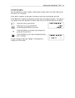
Press the F3 key to select MANUAL.
Press the F4 key to select PROGRAM.
An asterisk appears beside your choice.
Press the ENTER key to register your setting and to
proceed to the next menu.
Press the NEXT key if you wish to bypass this setting
with no changes.
If you do not wish to make any changes on the background
settings, turn off the plotter.
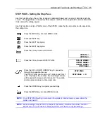
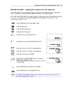
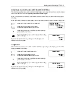
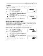
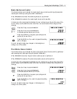
Initial Blade Control Position (INIT. BLADE CONTROL)
This function specifies the position at which initial blade control is performed (for more information
about initial blade control see
Adjusting the Blade Offset Angle
.)
When 2 mm BELOW is selected, initial blade control is performed 2 mm below the starting point
of cutting.
When OUTSIDE is selected, initial blade control is performed outside of the effective cutting area.
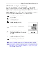
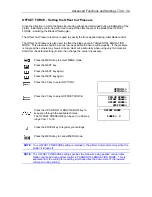
Press the F3 key to select 2 mm BELOW.
Press the F4 key to select OUTSIDE.
An asterisk appears beside your choice.
Press the ENTER key to register your setting and to
proceed to the next menu.
Press the NEXT key if you wish to bypass this setting
with no changes.
If you do not wish to make any changes on the background
settings, turn off the plotter.
Summary of Contents for Cutting Pro FC4100-100
Page 1: ...cutting pro FC4100 series series USER S MANUAL 1 a...
Page 138: ...Setting the Interface Functions C7 7 Input Output Circuitry Input Output Timing Chart...
Page 147: ...Specifications C8 6 FC4100 100 without Stand FC4100 100 with Stand Standard and Basket Option...
Page 148: ...Specifications C8 7 FC4100 130 without Stand FC4100 130 with Stand Standard and Basket Option...

