Setting the Interface Functions
♦
C7 - 6
Centronics-Compatible Parallel Interface
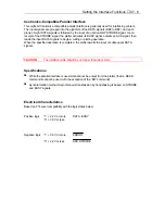
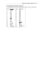
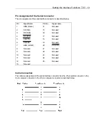
This eight-bit Centronics-compatible parallel interface is generally used for interfacing printers.
The input signals are grouped into the eight bits of the DATA signals (DB0 to DB7), and each
group of eight DATA signals is followed by the input of an active-LOW STROBE signal. Upon
receipt of the STROBE signal, the plotter activates its BUSY signal, outputs an ACK signal, then
reads the input DATA Signals to begin a cutting or plotting operation.
When the specified operation is completed, the plotter awaits the input of subsequent DATA
signals.
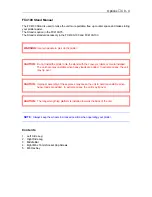
CAUTION:
The interface cable should be no longer than two meters.
Specifications
§
While the parallel interface is used, data cannot be output from the plotter (that is, READ
commands cannot be used with the exception of the “BS” command).
§
Synchronization method: Asynchronous transmission by handshaking is based on STROBE
and BUSY signals.
Electrical Characteristics
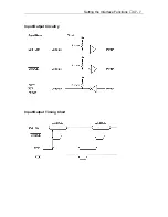
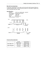
Based on TTL-level compatibility with the logic states below.
Positive logic
“1” + 2.2V or more
DATA, BUSY
“0” + 0.8V or less
Negative logic “1” + 0.8V or more
ERROR
“0” + 2.2V or less
ACK, STROBE
Summary of Contents for Cutting Pro FC4100-100
Page 1: ...cutting pro FC4100 series series USER S MANUAL 1 a...
Page 138: ...Setting the Interface Functions C7 7 Input Output Circuitry Input Output Timing Chart...
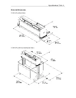
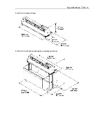
Page 147: ...Specifications C8 6 FC4100 100 without Stand FC4100 100 with Stand Standard and Basket Option...
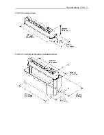
Page 148: ...Specifications C8 7 FC4100 130 without Stand FC4100 130 with Stand Standard and Basket Option...

