FC2240-UM-251-9730
3-11
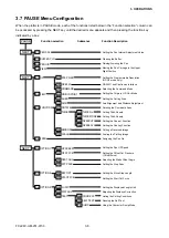
3. OPERATIONS
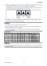
(7) When all of the displayed settings are correct, press the [ENTER] key to register the group of conditions
in the plotter’s internal memory. To change any of the settings, press the [NEXT] key.
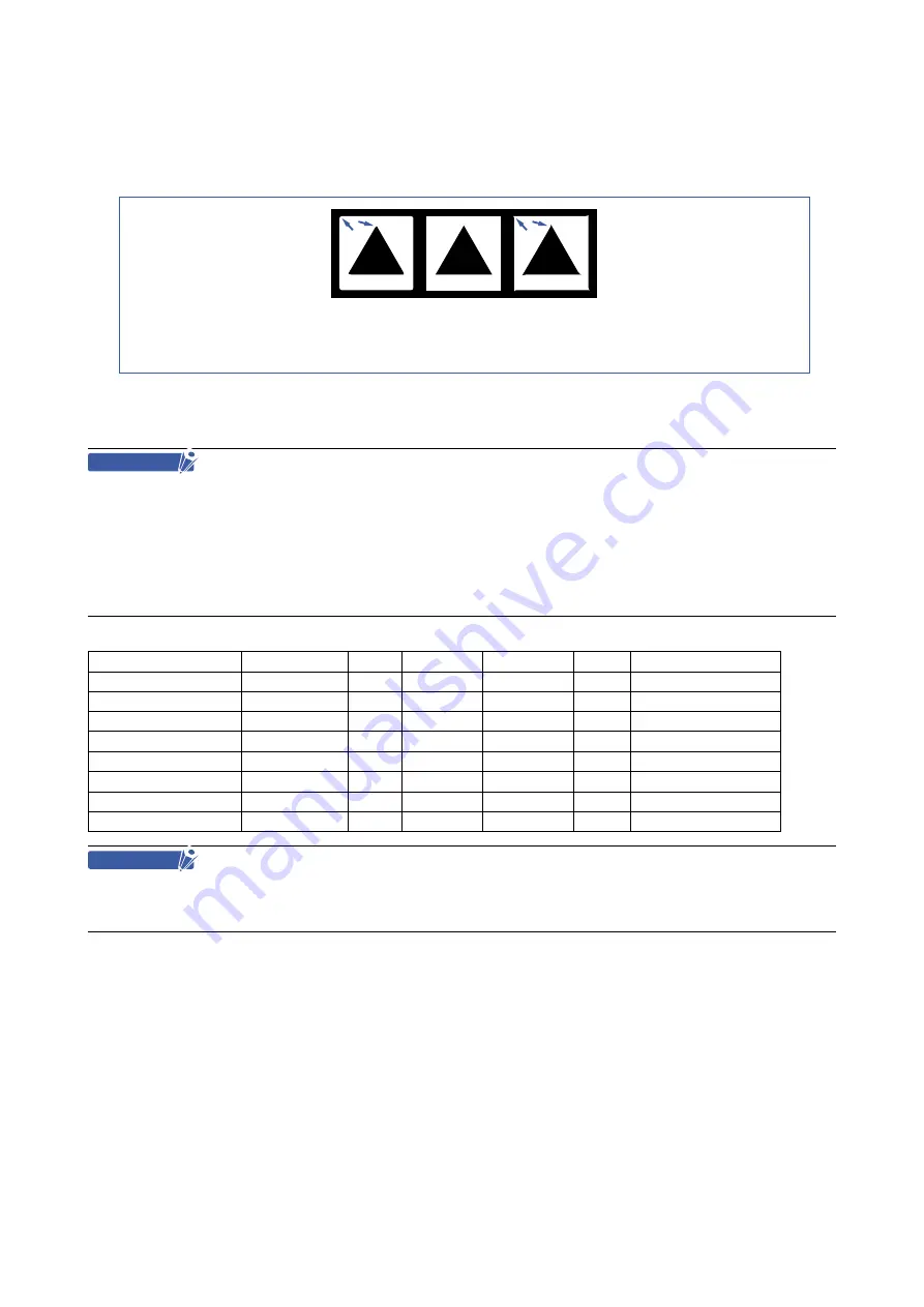
Use the [TEST] key to perform test cutting. Adjust the OFFSET value to suit the type and thickness of
the medium being used, and fine-adjust the finish of the corner sections.
OFFSET is too low.
Increase the
OFFSET value.
(+1 to +5)
OFFSET is too high.
Decrease the
OFFSET value.
(-1 to -5)
Correct
OFFSET
• If [OTHER] has been specified as the blade type, the OFFSET value can be set in a range of 1 to 45.
• The OFFSET value is not displayed for plotting mode.
CHECKPOINT
• Your settings are retained even while the plotter is turned off.
• Before you actually begin cutting, be sure to check that your cutting conditions are appropriately set as
described in Section 3.9 “Running a Cutting Test”.
• The FORCE and SPEED values, in particular, should be initially set to low values and gradually raised
while running cutting tests.
Factory Presets
Setting Condition No. Cutting force Speed Blade type Cutter offset Quality
Display mode
1
12
20
Pen
-
3
Plotter mode
2
14
20
09U
0
3
Cutter mode
3
17
20
15U
0
3
Cutter mode
4
12
20
Pen
-
3
Plotter mode
5
50
5
15U
0
1
Thick sheet mode
6
30
10
15U
0
3
Thick sheet mode
7
30
10
15U
0
3
Thick sheet mode
8
30
10
15U
0
1
Thick sheet mode
CHECKPOINT
In the initial settings, the setting condition numbers 1 to 4 are assigned to Pen 1, and the setting condition
numbers 5 to 8 to Pen 2.
Summary of Contents for FC2240
Page 1: ...CUTTING MACHINE SERVICE MANUAL FC2240 FC2240 UM 251 04 9370...
Page 2: ......
Page 8: ...FC2240 UM 251 9370 vi...
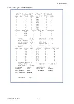
Page 38: ...FC2240 UM 251 9730 3 15 3 OPERATIONS Sample printout by the CONDITION function...
Page 42: ...FC2240 UM 251 9730 4 2 4 DAILY MAINTENANCE AND STORAGE...
Page 70: ...FC2240 UM 251 9370 7 26 7 DISASSEMBLY AND ADJUSTMENT...

