FC2240-UM-251-9370
7-5
7. DISASSEMBLY AND ADJUSTMENT
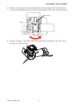
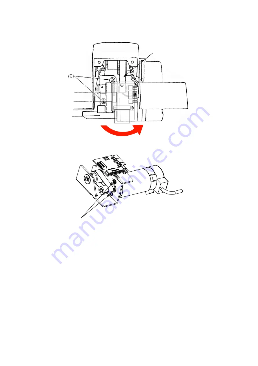
(4) As shown in the figure, remove the two M4 binding head screws indicated by the (C) arrows, then slip
the synchro belt indicated by the arrow off of the motor pinion gear and remove the entire motor bracket.
PN5042-02
Synchro belt
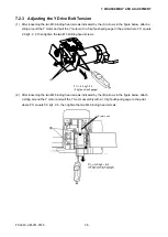
(5) As shown in the figure , remove the two M3 binding head screws (A) holding the Y-motor, then remove
the motor from the motor bracket.
(A)
Summary of Contents for FC2240
Page 1: ...CUTTING MACHINE SERVICE MANUAL FC2240 FC2240 UM 251 04 9370...
Page 2: ......
Page 8: ...FC2240 UM 251 9370 vi...
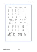
Page 38: ...FC2240 UM 251 9730 3 15 3 OPERATIONS Sample printout by the CONDITION function...
Page 42: ...FC2240 UM 251 9730 4 2 4 DAILY MAINTENANCE AND STORAGE...
Page 70: ...FC2240 UM 251 9370 7 26 7 DISASSEMBLY AND ADJUSTMENT...

