FC2240-UM-251-9370
8-5
8. ELECTRICAL ADJUSTMENTS
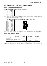
8.4 Checking the Power Unit’s Supply Voltage
8.4.1 Checking the Voltage Levels
(1) Use a multimeter to check the voltage levels of TP1 to TP5.
Voltage
TP1
+5V
TP2
+12V
TP3
+32V
TP4
-12V
TP5
+24V
(2) If voltage levels cannot be measured at TPI to TP5, use the following method to check the voltage levels.
• Disconnect the main board’s J101 connector.
• Next, use the multimeter to measure the voltage levels of the J101 connector pins.
Voltage
Pin 1
+5V
Pin 2
+12V
Pin 3
+32V
Pin 4
GND
Pin 5
GND
Pin 6
+5V
Pin 7
+12V
Pin 8
+32V
Pin 9
GND
Pin 10
GND
(3) If the measured voltage levels do not conform to the above tables, the power unit is probably defective.
8.4.2 The Protective Circuit
The protective circuit is activated in either of the following cases.
32 V power
5 V power
+12V power
-12V power
Protection against
excessive current
8 A or more
6 A or more
6 A or more
3A or more
Protection against
excessive voltage
115% of the rated
voltage (32 V)
----------
----------
----------
When the protective circuit is activated, all of the plotter’s supply voltages are switched off.
If the protective circuit is activated, turn off the plotter. After the plotter is left as is for three to five minutes, it
will automatically recover.
1
2
2
2
2
6
7
8
9
10
Summary of Contents for FC2240
Page 1: ...CUTTING MACHINE SERVICE MANUAL FC2240 FC2240 UM 251 04 9370...
Page 2: ......
Page 8: ...FC2240 UM 251 9370 vi...
Page 38: ...FC2240 UM 251 9730 3 15 3 OPERATIONS Sample printout by the CONDITION function...
Page 42: ...FC2240 UM 251 9730 4 2 4 DAILY MAINTENANCE AND STORAGE...
Page 70: ...FC2240 UM 251 9370 7 26 7 DISASSEMBLY AND ADJUSTMENT...


