background image

FC2240-UM-251-9370 

1-2

1. INTRODUCTION

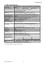
1.3 Main Specifications

FC2240-60VC

FC2240-120VC/MG/ES

FC2240-180VC/ES

Configuration

Flatbed

Effective cutting area

610 x 920 mm

1200 x 920 mm

1740 x 920 mm

Media hold-down method

VC models: Vacuum suction, MG models: Magnetic,

ES models: Electrostatic adhesion

Maximum cutting speed

400 mm/sec (40-step range)

Cutting force

High force mode: 9.8 N (1 kgf) max : 40-step range 2 to 80

Standard force mode: 4.9 N (500 gf) max : 40-step range 1 to 40

Minimum character size

About 10 mm square (varies with the character font and cutting media)

Mechanical resolution

0.0025 mm

Programmable resolution

GP-GL mode: 0.1/0.05/0.025/0.01 mm, HP-GL

TM

 mode: 0.025 mm

Distance accuracy

Within 0.1% of the distance moved (plotter mode)

Perpendicularity

Within 0.5 mm/900 mm (plotter mode)

Repeatability

Within 0.1 mm (plotter mode)

Number of pens/cutters

2

Cutter and pen types

Cutter blades: Supersteel

Pens: water-based fibertip, oil-based ballpoint, disposable ink pen

*1

Cutting media

Marking film (vinyl, fluorescent, reflective), Stiff paper/card up to 0.5 mm 

thick, Sandblast rubber sheets up to 1 mm thick, High-intensity reflective 

film. Polystyrene foam sheets

Interfaces

RS-232C, Centronics, USB 2.0 (full speed); auto-switching

Buffer memory

2 MB

Command sets

GP-GL and HP-GL

TM

 emulation

LCD panel

20 characters x 2 lines

Power supply

100-120 VAC, 50/60 Hz, 1.2 A max

220-240 VAC, 50/60 Hz, 0.7 A max

Operating environment

10 to 35˚C, 35 to 75% RH (non-condensing)

Guaranteed precision 

operating environment

16 to +32˚C, 35% to 70% RH (non-condensing)

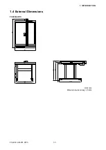
External dimensions
(H x W x D)          Horizontal 857  x 920 x 1285 mm

944 x 1568 x 1285 mm 944 x 2068 x 1285 mm

Tilted

----

*2

1687 x 1568 x 987 mm

1687 x 2068 x 987 mm

Weight (including stand)

Approx. 58 kg

Approx. 69 kg

Approx. 74 kg

Option

Vacuum pump (Blower) [VC models only]

*1: Disposable ink pens cannot be used with the high-force pen (Pen 2 holder).

*2: The writing panel on VC models cannot be tilted.

Summary of Contents for FC2240

Page 1: ...CUTTING MACHINE SERVICE MANUAL FC2240 FC2240 UM 251 04 9370...

Page 2: ......

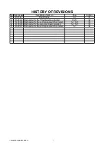
Page 3: ...4 First Printing All 01 2 06 04 24 Part number for the Y flexible cable corrected 10 10 02 3 06 05 26 Part number for the control panel switch corrected 5 1 10 5 03 4 06 05 26 Part number for the main...

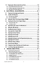
Page 4: ...2 Control Panel 2 2 2 3 Types of Cutter Blades and Their Features 2 4 2 4 Cutter Pen Nomenclature 2 5 3 Basic Operation 3 1 3 1 Replacing the Cutter Blade 3 1 3 2 Adjusting the Blade Length 3 3 3 3 M...

Page 5: ...e Y Slider 7 7 7 3 1 Removing the Y Bar 7 7 7 3 2 Adjusting the Y Slider Belt Tension 7 8 7 4 Adjusting the Roller Pressure of the Front X Slider 7 9 7 5 Adjusting the Roller Pressure of the Rear X Sl...

Page 6: ...oard 8 6 8 6 Setting the DIP Switches 8 7 8 7 Updating the System Firmware 8 8 8 8 Clearing the Non Volatile RAM 8 10 8 9 Adjusting the Home Position 8 12 8 10 Adjusting the Pen Height 8 13 8 11 Adjus...

Page 7: ...10 5 10 5 X Drive Unit 10 6 10 6 Y Drive Section 10 9 10 7 Standard Accessories 10 12 11 BLOCK DIAGRAMS AND CIRCUIT DIAGRAMS 11 1 11 1 Wiring Connection 11 1 11 2 Key Relay Board PR223281 11 3 11 3 Ma...

Page 8: ...FC2240 UM 251 9370 vi...

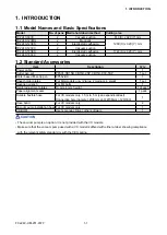
Page 9: ...set Water based ber tip pen KF552 BK 1 Sheet holder plates For MG models only 2 large 2 medium 4 small 1 set Hexagon wrench For M4 bolts 1 Height adjustment plates 10 mm 4 mm height 1 of each Paper a...

Page 10: ...tter and pen types Cutter blades Supersteel Pens water based fibertip oil based ballpoint disposable ink pen 1 Cutting media Marking film vinyl fluorescent reflective Stiff paper card up to 0 5 mm thi...

Page 11: ...FC2240 UM 251 9370 1 3 1 INTRODUCTION 1 4 External Dimensions FC2240 60VC 1285 920 720 910 857 790 67 58 1040 Unit mm Dimensional accuracy 5 mm...

Page 12: ...FC2240 UM 251 9370 1 4 1 INTRODUCTION FC2240 120 Unit mm Dimensional accuracy 5mm 526 877 944 67 1687 5 8 9 0 4 0 1 1 0 1 2 7 0 0 1 1 2 6 1 8 6 5 1 1285 FC2240 120...

Page 13: ...FC2240 UM 251 9370 1 5 1 INTRODUCTION FC2240 180 Unit mm Dimensional accuracy 5mm 526 877 944 67 1687 5 8 9 0 4 0 1 1 0 1 2 7 0 0 6 1 2 6 1 8 6 0 2 1285 FC2240 180...

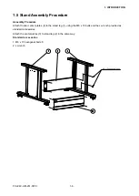
Page 14: ...Procedure Attach the two center plates 3 to the stand leg 1 using the M6 x 15 bolts and the L wrench provided as standard accessories Attach the center plates 3 to stand leg 2 in the same way Standard...

Page 15: ...tand insert the cables protruding from the underside into the control panel box The control panel box is affixed to the side of the stand with four M3 x 8 screws at the top and two at the bottom To fa...

Page 16: ...ning brackets to the front in a horizontal direction Next pull the brackets out in an upward direction Use the L wrench supplied as a standard accessory CAUTION IMPORTANT Move the plate nuts inside th...

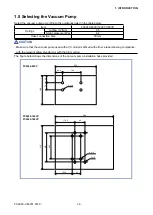
Page 17: ...essure kPa 6 4 Hose connection bore 50 mm CAUTION Make sure that the vacuum pump used with a VC model is af xed with either a label showing compliance with the relevant safety standard or with the CE...

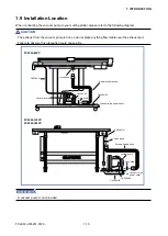
Page 18: ...o do not place anything ammable near the exhaust port Failure to observe this precaution could cause a re Hose band Hose band CA2294 03 CA2294 02 CA2294 01 Vacuum pump Durable flexible hose Connect to...

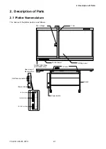
Page 19: ...clature The names of the plotter parts are as follows Pen carriage Y ber Control panel Tilt lever CHART HOLD key ES models only Writing panel Stand Power switch Power inlet Interface connector Rear vi...

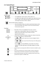
Page 20: ...y Shift the cursor when setting a numeric value for a function Select the desired submenu All four keys are used to move the pen carriage when setting a function that requires the speci cation of a co...

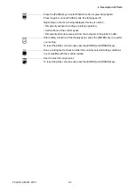
Page 21: ...functions at the control panel Temporarily store data received from the computer in the plotter s buffer After setting a function at the display panel press the ENTER key to register your setting To...

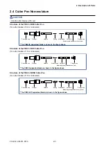
Page 22: ...K30 1 5 CB15U SP 1 5 CB15U K30 SP 1 5 CB09UA 0 9 Less expensive than other types of blades The maximum cutting distance is about 4000 m depending on the medium and cutting pressure used The spring en...

Page 23: ...cap Blade length adjustment knob blue Structure of the PPA31 CB15 Cutter Pen for cutter blades of 1 5 mm diameter Protective cap Plunger Holder A Cutter blade Holder B Plunger cap Blade length adjust...

Page 24: ...de replacement varies with the type of cutter pen used Color of the blade length adjustment knob Blue PPA31 CB09 cutter pen for 0 9 mm blades 1 Remove holder B by turning the blade length adjustment k...

Page 25: ...is insuf ciently lubricated In this case apply the grease provided to the three points indicated by arrows in the gure CAUTION Be careful not to stab your nger at this time Color of the blade length a...

Page 26: ...how far to move the blade When the knob is turned the distance of one scale unit the blade moves 0 1 mm When it is given one full turn the blade moves 0 5 mm 2 Align the blade tip with the tip of the...

Page 27: ...Loosen the pen holder screw and mount the pen 2 After mounting the pen tighten the screw Mount each of the pens in the same way as that used for 1 pen models When facing the pens the left pen is desi...

Page 28: ...the pen carriage is parallel to the writing panel 4 When the adjustment is complete remove the height adjustment plate thick from under the pen carriage S Height adjustment during cutter pen installa...

Page 29: ...trical outlet of the speci ed voltage 4 Press the I ON side of the power switch 5 The green power lamp on the control panel will light and the Y bar and pen carriage will start to move as shown in the...

Page 30: ...ng panel 2 Secure the edges of the medium with the steel holder plates which are supplied with your plotter as standard accessories Vacuum suction models feature a green writing panel 1 Place the medi...

Page 31: ...Cutting Thick Sheets Cutting Thick Sheets Setting the Overcut Function Setting the Overlay Function Cutting a Reversed Image Scaling the Plotting Image Assigning the Pen No Setting the Pen UP Speed S...

Page 32: ...SET QUALITY The description of each cutting condition is as follows FORCE Sets the pressure to be applied by the cutter blade or pen tip against the loaded medium during cutting or plotting SPEED Sets...

Page 33: ...e below is displayed In this example the factory default setting COND 2 has been selected Items displayed may differ for other COND numbers FORCE OFFSET SPEED QUALITY Blinking cursor 14 COND2 09U 0 20...

Page 34: ...mode CHECKPOINT Your settings are retained even while the plotter is turned off Before you actually begin cutting be sure to check that your cutting conditions are appropriately set as described in S...

Page 35: ...CUTTING PRO When the F2 key CUTTING PRO is pressed the display changes to the CUTTING PRO prompt menu TEST2 As soon as the F3 key TEST2 is pressed three triangles within squares are consecutively cut...

Page 36: ...el CB09UA CB15U CB15U SP 14 to 17 30 or less 3 outdoor 0 05 to 0 1 10 to 14 30 or less 3 Fluorescent lm 0 2 to 0 25 16 to 20 30 or less 3 Masking lm for block copy production 0 01 to 0 1 CB15U K30 CB1...

Page 37: ...nted in the pen holder Load a sheet of paper that is A4 in size or larger Procedure Replace the cutter pen at the pen carriage s pen holder with a plotting pen and load paper in the plotter 1 Press th...

Page 38: ...FC2240 UM 251 9730 3 15 3 OPERATIONS Sample printout by the CONDITION function...

Page 39: ...ss the NEXT key twice more 4 Press the F4 key to select OPTION 2 5 Press the F4 key to select TEST 6 Press the F4 key to select DUMP The prompt message below appears FORCE OFFSET SPEED QUALITY Blinkin...

Page 40: ...vicinity of the pen carriage and Y bar Procedure Replace the cutter pen at the pen carriage s pen holder with a plotting pen and load paper in the plotter 1 Press the PAUSE key to select PAUSE mode 2...

Page 41: ...s they may damage the casing s nish 3 If the writing panel surface is soiled wipe it with a dry cloth If the surface is extremely dirty dampen the cloth with a diluted solution of neutral detergent or...

Page 42: ...FC2240 UM 251 9730 4 2 4 DAILY MAINTENANCE AND STORAGE...

Page 43: ...r 1 6 772247550 Y Motor 1 7 510000051 Power Supply PS0089B 1 Same as FC2230 8 162291230 X Flexible Cable FCA2291023 1 FC2240 60 120 162291240 X Flexible Cable EX FCA2291123 1 FC2240 180 9 162291100 Y...

Page 44: ...2 Phillips screwdriver M4 13 Phillips screwdriver M3 14 Phillips screwdriver M2 15 Small flat head screwdriver For adjusting the variable resistors on the board 16 Hexagon wrench 1 5 mm span For M3 se...

Page 45: ...Tension 1 Remove the rear left corner cover 2 After loosening the two M3 binding head screws indicated by the B arrows attach a string around the X motor and pull the X motor with a 5 kgf push pull ga...

Page 46: ...check that the belt at the pulley section is balanced right and left If not repeat steps 2 to 4 above so that the belt is balanced 7 1 4 Adjusting the Belt Tension of the Rear X Slider 1 Remove the r...

Page 47: ...e the tilt lever bracket to avoid touching the belt 3 Pull the X belt 20 mm from the X rail in the center of the X belt using a 1 kg push pull gauge The pull force should be FC2240 60 FC2240 120 FC224...

Page 48: ...the direction indicated by the arrow 7 2 2 Removing the Y Motor 1 Remove the three M3 binding head screws holding the X FPC Flexible Printed Circuit cable holder then remove the X FPC cable holder 2...

Page 49: ...ad screws indicated by the C arrows then slip the synchro belt indicated by the arrow off of the motor pinion gear and remove the entire motor bracket PN5042 02 Synchro belt 5 As shown in the gure rem...

Page 50: ...a 5 kgf pushpull gauge to the point where FY1 equals 2 0 kgf 0 2 then tighten the two M3 binding head screws FY1 2 0 kgf 0 2 5 kgf push pull gauge A 2 After loosening the two M4 binding head screws i...

Page 51: ...then pull out the X FPC cable connector from the X relay board The pen block should be removed first 2 Remove the 5 mm bind screw and the countersunk head screw indicated by the A arrows A 3 After re...

Page 52: ...binding head screws D so that the belt is balanced right and left Turn the screws to the right to tighten the belt Turn the screws to the left to loosen the belt 3 Check the Y slider belt tension Sli...

Page 53: ...where the rollers contact the front X rail 3 Using the three screws indicated by A apply pressure to the rollers by adjusting the rollers so that they are parallel to the sliding surface 4 Tighten the...

Page 54: ...ot scratched by the edge of the rear X rail 3 Adjusting the horizontal roller pressure After adjusting the screws indicated by A and B be sure to lock them in place with adhesive After tightening scre...

Page 55: ...e preceding gure to move the rollers into contact with the sliding surface of the rear X rail then secure the nuts with adhesive NOTES 1 Con rm the horizontal roller pressure by visually checking that...

Page 56: ...Y slider and temporarily secure it in that position 2 Adjusting the Y slider s roller pressure With the Y slider oriented as shown in the gure above insert it onto the Y bar then move each roller back...

Page 57: ...1 9370 7 13 7 DISASSEMBLY AND ADJUSTMENT 7 7 Adjusting the Position of Sensor Dog Y Align the sensor dog Y A with the center of the Y sensor s slit then apply adhesive to secure the sensor dog Y in th...

Page 58: ...ble through the FPC guide B shown in the gure below then insert the FPC cable into the connector 3 Secure the board bracket to the Y slider using the screw which was removed in Step 1 above 4 Attach d...

Page 59: ...the two M3 binding head screws then lift the cover up in the direction indicated by the arrow 7 9 2 Removing the Pen Block 1 Pull out the CA2293 39 cable from its connector on the PR223229 2 pen relay...

Page 60: ...pressure of the 692ZZ bearing against the guide shaft may be too high Also check for foreign matter on the parts concerned When the slide arm is pressed down by hand it should lower smoothly 2 If the...

Page 61: ...e there is no gap Secure with the M2 set screws Offset pin 692ZZ bearing M2 set screw Guide shaft 4 Checking the guide shaft and bearing adjustment Raise or lower the guide shaft of the slide arm and...

Page 62: ...FC2240 UM 251 9370 7 18 7 DISASSEMBLY AND ADJUSTMENT 7 10 Using the Mechanical Adjustment Jigs 1 Pen block height adjustment jig standard accessory...

Page 63: ...Y bar 2 Remove the Y bar 3 Attach a new Y bar Temporarily attach the Y bar along the line drawn in Step 2 of subsection 7 11 1 Preparations Adjust the Y bar height from the front frame and rear frame...

Page 64: ...the Y bar frame Loosen the screw located on the bottom plate of the control panel then pull the control panel assembly toward you to increase the clearance When the front and back clearances of the Y...

Page 65: ...to plot the pattern shown in the gure below 3 Turn the sheet over and load it so that points A and B on the other side are parallel to the X axis 4 After positioning the pen on point D draw a line to...

Page 66: ...ty cannot be satisfactorily adjusted by performing the preceding Steps 1 to 6 repeat adjustment after loosening the two 3 mm setscrews indicated by the E arrows 8 You will be able to adjust the perpen...

Page 67: ...like makes it easy 5 Remove any remaining double sided tape and glue Sprinkle on ECT 1 toner cleaning uid available from Graphtec and leave for 1 or 2 minutes Scrape off with some sort of scraper e g...

Page 68: ...as close to these widths as possible Tape on lengthwise strips of wide double sided tape at intervals of 5 mm NOTE Never let the tape overlap Tape on the double sided tape in such a way that the gap...

Page 69: ...ul not to let any dirt or dust get under the electrostatic adhesion plate during positioning 2 Secure the origin side with strong tape 3 Peel off and fold back the backing sheet of the double sided ta...

Page 70: ...FC2240 UM 251 9370 7 26 7 DISASSEMBLY AND ADJUSTMENT...

Page 71: ...Unit s Supply Voltage 8 4 Checking the Power Unit s Supply Voltage 8 6 Setting the DIP Switches 8 9 Adjusting the Home Position 8 10 Adjusting the Pen Height 8 11 Adjusting the Pen Force 8 12 Adjustin...

Page 72: ...FC2240 UM 251 9370 8 2 8 ELECTRICAL ADJUSTMENTS 8 2 Location of the Boards 8 2 1 Main Board PR306101 J9 J10 J2 J1 JP3 JP4 P3 P11 P12 TP7 TP6 TP5 J3 P31 P21 J101 P1 P52 P31 P22 J4 P32 P42 J6 SW1...

Page 73: ...FC2240 UM 251 9370 8 3 8 ELECTRICAL ADJUSTMENTS 8 2 1 Main Relay Board PN5042 01 JP6 Jumper switch setting of JP6 8 2 2 X Flex Board PR223226 JP1 Jumper switch setting of JP1...

Page 74: ...s Supply Voltage PS089B 1 Check that the plotter s POWER switch is off 2 Remove the upper chassis of the Control Unit 3 Connect the power unit s cable to the required connector Voltage series Correspo...

Page 75: ...n 5 GND Pin 6 5V Pin 7 12V Pin 8 32V Pin 9 GND Pin 10 GND 3 If the measured voltage levels do not conform to the above tables the power unit is probably defective 8 4 2 The Protective Circuit The prot...

Page 76: ...f an example are shown below PEN1 88 424 732 PEN2 89 424 772 1030 1533 X 10 Y 0 D 860 00 Explanation of the values Pen force values PEN1 24g 210g 400g PEN2 24g 210g 400g 700g 1000g Distance adjustment...

Page 77: ...de Set bits 2 3 5 6 and 7 to ON 1 2 3 4 5 6 7 8 ON OFF Initialize the main board by clearing the non volatile RAM Execute this function before starting any electrical adjustment Electrical Adjustments...

Page 78: ...ectrical Adjustment mode 3 Hold down both the Right and Left POSITION keys while turning on the power When you hear a short buzzer tone release the keys The LCD should display the following UPDATE FIR...

Page 79: ...he transfer is completed the display automatically changes to FLASH MEMORY CLEAR and FLASH MEMORY WRITE and the system begins writing to ash memory Note If you are writing to a new board the system wi...

Page 80: ...AM INIT 100 CLEAR message is displayed a menu for model selection appears on the LCD panel SET FC TYPE FC2240 60 2 4 Select your plotter model using the the and keys and then press the ENTER key to re...

Page 81: ...ed and then press the ENTER key to register your plotter standard setting SET SUFFIX STD V 1 00 8 After the COMPLETED message is displayed as shown below turn off the plotter and then return the DIP s...

Page 82: ...he following MOVE HOME POINT PRESS ENTER KEY 4 Attach a pen type magni er to the No 1 pen holder and then move it to the desired home position using the POSITION keys After con rming the position pres...

Page 83: ...l the LCD displays the following PEN HEIGHT PRESS ENTER KEY 4 Press the Enter key The LCD screen changes to display the following AUTO ADJ DEFAULT POWER 5 Press the F1 AUTO ADJ key After the message b...

Page 84: ...measure the pen pressure with a Colex gauge Use the F1 through F4 keys to adjust the pen pressure until the pressure is within 24 1 g After adjustment press the Enter key to go to the next step If yo...

Page 85: ...ustment menu and then return the DIP switch to its normal settings NOTE After you have changed the numeric value on the LCD press the F3 key PEN U D to raise and lower the cutter before measuring the...

Page 86: ...5 6 7 8 ON OFF 4 Turn on the power to the plotter 5 Press the NEXT key until the following menu is displayed DIST ADJ 0 01mm PRESS ENTER KEY 6 Press the Enter key to display the menu shown below SEl...

Page 87: ...value in 0 1 mm steps F4 key 0 01 Decrease the diagonal distance value in 0 01 mm steps 13 Input the diagonal adjustment values using the F1 to F4 keys The displayed L value is the diagonal distance I...

Page 88: ...positions 5 When the TEST key is pressed the lines shown below are drawn 6 Adjust the deviation of Pen 1 based on the lines drawn by Pen 2 To adjust the X axis deviation press the F2 key and then use...

Page 89: ...the following messages appear on the LCD panel turn off the plotter NOVRAM CLEAR START NOVRAM CLEAR END 3 After turning the plotter back on and waiting until it has been initialized check that the plo...

Page 90: ...y to select PAUSE mode 2 Press the NEXT key 3 Press the NEXT key again I F FUNCTION FILM 2PEN 4 Press the F1 key to select INTERFACE RS 232C STEPSIZE COMMAND 5 Press the F4 key to select COMMAND COMMA...

Page 91: ...T 0 0 0 0 0 0 0 0 0 0 0 N 0 0 0 0 0 0 TEST 0 0 0 0 0 0 0 0 0 0 T 0 0 0 0 0 0 0 ENTER 0 0 0 E 0 0 0 0 0 0 0 0 0 0 0 0 0 0 CONDITIONS 0 0 C 0 0 0 0 0 0 0 0 0 0 0 0 0 0 0 COPY 0 P 0 0 0 0 0 0 0 0 0 0 0 0...

Page 92: ...tting mat may be damaged and a position error may be caused by the pen block striking the side plate 3 If a panel key s corresponding bit does not properly change status check the following Fault in D...

Page 93: ...oard X home sensor Y home sensor Pen block X Y motor X Y Motor drive belt NOV RAM clear and model selection M Firmware upgrade N Pen height adjustment M M M Pen force adjustment M M Distance adjustmen...

Page 94: ...moothly Rotate the blade with your nger No Yes Check the cutter plunger Is the spring attached to the blade PPA31 CB09 15B No Mount the spring so that it will not come off the blade Is there grease on...

Page 95: ...there play or a strange sound in the mechanical section See section 9 1 1 Checking for Faulty Rotation of the Blade Yes Check the cutter setting conditions Cutter offset for the blade type Blade leng...

Page 96: ...of the media 0 1 mm Yes Lower the cutting speed to 24 or lower Problems with the media Extremely soft Weak adhesion to backing sheet Other problems No No Check with cutter loupe Yes Is the accelerati...

Page 97: ...ting speed to 24 or lower There is a problem with the medium It is too hard No No Yes Is the acceleration high 4 or more Lower the acceleration to 3 or less Yes Is the cutting force low 9 or lower No...

Page 98: ...plotter mode normal The cut shape differs from the speci ed shape No Yes Is the interface setting correct Set the interface on the control panel Incorrect command selection Specify the commands that m...

Page 99: ...the acceleration 4 or more Line waver No Yes Is the X belt tension too low Adjust the belt tension Some lines waver so lower the acceleration Yes Replace the X and Y motors No Is the synchro belt loo...

Page 100: ...and grease deterioration See section 9 1 1 Checking for Faulty Rotation of the Blade Yes No Is there unevenness or air in the cutting media When the pen is raised the blade tip touches the cutting med...

Page 101: ...the X direction Yes Faulty X home sensor Replace main board No No Yes Does the READY message appear and do all control panel keys operate properly Faulty keyboard Faulty cable Faulty main board Yes No...

Page 102: ...ng procedures Part 1 Is there play or does it get stuck Use your nger to gently move the pen holder up and down No Yes Is the guide shaft bearing pressure faulty Play in the slide shaft or its bearing...

Page 103: ...er Repair the pen block or adjust the pen servos of the replacement main board Yes No Readjust the main board s pen servos Manually move the pen holder up and down Is the speci ed voltage being correc...

Page 104: ...Does the Y slider rattle Replace the pen block assembly Remove the Y bar and adjust the Y slider roller pressure Yes No No Check the M2 setscrew holding the pen holder and the thumb screw and tighten...

Page 105: ...0 UM 251 9370 9 12 9 TROUBLESHOOTING 9 1 6 The Y axis Backlash is Excessive 1 Adjust the perpendicularity of the Y bar see section 7 12 Adjusting the Perpendicularity Precision 2 Adjust the Y belt ten...

Page 106: ...s AC line inlet and the electrical output The plotter is defective Check the main board and connectors The control panel s POWER lamp lights but the plotter does not operate The control panel s PAUSE...

Page 107: ...tem 3 3 Is the X or Y exible cable securely connected No Connect it securely Yes Replace the X or Y exible cable if defective Home sensor or sensor plate adjustment 4 Is the X or Y home sensor plate p...

Page 108: ...plotter No Set the correct model name Con gure your software application menu to permit Graphtec plotter control Re specify the software application s interface conditions ERROR 4 PARAMETER OVERFLOW...

Page 109: ...recognizable command No Verify item 2 Yes Send correct data to plotter 2 Is there any noise on the line No Verify item 3 Yes Check the interface cable or move the plotter to another location 3 Has the...

Page 110: ...er output command was executed Check the ow of your programmed data ERROR 11 Invalid byte following ESC The ESC character was followed by an invalid byte Check the ESC commands in your program ERROR 1...

Page 111: ...mpletely cut lines that should be solid Solid lines are not cut at a constant depth The blade is extended too far Adjust the blade length The cutting SPEED is too high Lower the SPEED setting Coarse r...

Page 112: ...lotter and software to the same resolution The computer sent coordinate data that exceeds the speci ed effective cutting area Set the effective cutting area to a larger area The computer sent coordina...

Page 113: ...anel 120 FC2240 120VC 772293040 Vacuum Panel 180 FC2240 180VC 3 022907302 Power Board Cover 1 4 621474110 Corner Cover Front Right 1 5 022907391 Support Bracket 4 M4 18 6 022907291 Support Bracket 8 M...

Page 114: ...FC2240 UM 251 9370 10 2 10 PARTS LIST Mainframe 17 16 E2 E4 14 13 E1 14 15 15 10 9 12 2 E3 3 4 5 6 7 1 8 E5...

Page 115: ...054221031 Rear Main Bar 60 1 FC2240 60 622301800 Rear Main Bar 90 FC2240 120 622301760 Rear Main Bar EX FC2240 180 4 054221021 Front Main Bar 60 1 FC2240 60 622301790 Front Main Bar 120 FC2240 120 62...

Page 116: ...772232020 LCD 1 E3 122907010 Control Cable 1 CA2290 01 1 682247030 Sheet Switch 1 PN5042 03 2 621476000 Panel Frame 1 3 022901330 Tray 60 1 FC2240 60 022900742 Tray 120 FC2240 120 022900750 Tray 180...

Page 117: ...Part No Description Q ty Remarks 1 508102306 Power Switch 1 SW 2WI36 92 2 518000033 AC Inlet 1 SUP B3G E 3 792240700 Main Board 1 4 792240701 Main Relay Board 1 5 510000051 Switching Power Supply 1 P...

Page 118: ...25 022903133 Intermediate Shaft 1 27 022900360 Drive Collar C 1 28 022903250 Pulley 1 99Z TN 29 375311001 Notched Synchro Belt 1 120TN15 30 022900351 X Gear Space Board 1 32 621472200 X Motor Cover 1...

Page 119: ...0 UM 251 9370 10 7 10 PARTS LIST No Part No Description Q ty Remarks 60 022904540 XR End 1 61 022904560 XR Pulley Bracket 1 62 022904530 XF End 1 63 022904550 XF Pulley Bracket 1 64 622301630 Belt Pla...

Page 120: ...LIST X Drive Unit 29 28 27 27 44 56 32 20 16 17 18 23 30 21 44 33 34 35 36 38 64 46 43 41 10 6 45 49 51 45 4 49 51 4 6 12 8 7 7 55 54 54 14 13 11 8 8 8 9 52 53 53 10 10 E3 5 3 63 62 61 60 3 5 4 3 42...

Page 121: ...20 Bearing 2 F608ZZ 31 022904250 Y Stopper 1 40 022904022 Y Slider 1 41 621473310 Plate PUF 1 42 022904131 Offset Pin A 2 43 022904151 Offset Pin C 2 44 022904311 GND Plate 1 45 022904171 Board Bracke...

Page 122: ...Board 1 PR223229 Assembly E4 305320007 Moving Coil 3 PL 326B E5 110006060 MC Flexible Cable 1 FPC10002 E6 792240702 Height Sensor 2 E7 772230310 Y Limit Switch Assembly 1 PR229008 Assembly E8 77223213...

Page 123: ...62 71 70 E5 E4 65 60 9 74 E2 E3 44 52 49 40 55 48 49 49 52 53 50 20 46 29 47 30 28 21 22 C C D D 23 31 26 25 27 24 43 53 27 51 72 73 E11 E10 64 E6 E6 41 54 10 10 E1 12 2 13 4 8 E8 45 E9 55 55 E7 15 1...

Page 124: ...02200020 Hexagonal Wrench 2 5 1 7 AC Power Cable 1 8 972100151 PPA31 CB15B 1 9 972100300 CB15U 2SP 1 10 972100320 CB15U K30 5SP 1 11 947000051 KF550 F6 1 12 915052360 PL525 A2 KP 1 13 302200102 Flexib...

Page 125: ...A 4 GND 3 X HOMEZ 2 GND 1 5V 4 X EN B 3 X EN A 2 GND 1 5V 3 GND 2 X HOME Z 1 5V 2 XM 1 XM 1 GND 2 GND 3 KEY0 4 KEY1 5 KEY2 6 KEY3 7 KEY4 8 KEY5 9 KEY6 10 KEY7 11 PAUSE LED 12 PROMPT LED 13 PAUSE Z 14...

Page 126: ...N B 28 GND 29 Y EN A 30 GND 31 YM 32 YM 33 YM 34 YM 1 MC1 2 MC1 3 GND 4 PLFB 2 5 12V 6 12V 7 GND 8 MC2 9 GND 10 MC2 11 GND 12 Y HOME Z 13 PLFB 1 14 5V 15 GND 16 Y EN B 17 GND 18 Y EN A 19 GND 20 YM 21...

Page 127: ...11 10 9 8 7 6 5 4 3 2 1 P101 FL1 FL2 FL3 FL4 FL5 FL6 FL7 FRC5 C34L53T OL DSS306 102M DSS306 102M DSS306 102M DSS306 102M DSS306 102M DSS306 102M DSS306 102M 5V 5V 5V 5V D1 1SS254T 77 1SS254T 77 D2 R1...

Page 128: ...21 22 23 24 25 26 27 28 29 30 31 32 33 34 34V 34V C HLD GND MC1 MC1 MC1 MC1 GND GND PLFB2 GND 12V GND 12V GND PLFB1 GND MC2 MC2 MC2 MC2 YHOMEZ GND 5V 5V YENB GND YENA GND YM YM YM YM JP3 RF H082TD 119...

Page 129: ...U1 HC14 7 14 U2 HC74 U2B 74HC74 12 11 9 8 10 13 D CLK Q Q PR CL U3B NJM072B 5 6 7 U1B 74HC14 3 4 U3A NJM072B 3 2 1 8 4 D1 V06C R6 10K C9 104 Q2 2SC1815 RLY2 G5V 1 DC12V 9 1 10 N 0 N C N 0 N 0 N C N C...

Page 130: ...PR223203 P31 5V GND XHOMEZ GND XENA GND XENB GND GND GND XM XM XM XM 1 2 3 4 5 6 7 8 9 10 11 12 13 14 FL1 5V FRC5 C14L53T OL FL2 FBR07HA P301 IL G 2P S3T2 E IL G 4P S3T2 E IL G 3P S3T2 E 1 2 XM XM P30...

Page 131: ...25 24 23 22 21 20 19 18 17 16 15 14 13 12 11 10 9 8 7 6 5 4 3 2 1 34V 34V C HPLD GND MC1 MC1 MC1 MC1 GND GND PLFB2 GND 12V GND 12V GND PLFB1 GND MC2 MC2 MC2 MC2 YHOMEZ GND 5V 5V YENB GND YENA GND YM...

Page 132: ...6 U1A NJM4558 1 8 4 2 12V J503 IL G 3P S3L2 E IL G 4P S3L2 E IL G 2P S3L2 E J502 J501 52044 2345 1 2 3 4 5 6 7 8 9 10 11 12 13 14 15 16 17 18 19 20 21 22 23 1 2 3 4 1 2 3 5V YHOMEZ GND 5V GND YENB YE...

Page 133: ...OCK DIAGRAMS AND CIRCUIT DIAGRAMS 11 7 Pen Flex Board PR223226A J61 52044 1010 IL 6 10P S3L2 E P62 MC1 MC1 GND PLFB2 12V 12V PLFB1 GND MC2 MC2 10 9 8 7 6 5 4 3 2 1 MC1 MC1 GND PLFB2 12V 12V PLFB1 GND...

Page 134: ...LOCK DIAGRAMS AND CIRCUIT DIAGRAMS 11 8 2 Pen Relay Board PR223229A P91 IL G 10PS3L2E IL G 10PS3L2E P92 MC1 MC1 FG 12V 12V SG PLFB1 PLFB2 MC2 MC2 MC1 MC1 FG 12V 12V SG PLFB1 PLFB2 MC2 MC2 1 2 3 4 5 6...

Page 135: ...221 470K 470K 15K R10 15K 103 C5 103 U1A U1B 1 3 8 4 2 7 6 4 8 5 NJM4558 NJM4558 12V 12V 12V C1 R6 R3 R1 C7 221 470K 470K 15K R2 15K R4 R5 R7 200 R8 1K 2 2K 11K U2B 7 6 4 8 5 NJM4558 12V R12 R13 R15...

Page 136: ...10 High Voltage Board PR31001C 24V GND OPEN 1 2 3 C1 22uF 35V C2 HVT 10uF 15V C4 D1 471 6KV C5 R5 510K R6 1 2 3 V PPEN GND 1625 03R 510K 471 6KV R1 R3 D5 D5 1S1585 D2 TFR2T TFR2T D3 1S1585 RD4 7E R2...

Page 137: ...KCONT2Z YHOMEZ PA X PENSEL TMBSEL OSDCSZ OSDSCK OSDSIN B WZ RSNS ROLL INRZ RESERVE IF Value TXD0 RTS0Z DTR0Z TXD1 RXD0 CTS0Z DSR0Z RXD1 A 21 1 RDZ WRLZ CENCSZ RESET D 15 0 CENINTZ KEYB 7 0 KCONT2Z TM...

Page 138: ...2 SN75189A 1 4 10 13 2 5 9 12 3 6 8 11 7 14 1A 2A 3A 4A C1 C2 C3 C4 1Y 2Y 3Y 4Y GND VCC C15 102 C13 102 P21 B2B XH A B3B XH A 1 2 3 U3A 74LS06 1 2 RA1 470 4 FL5 EXCCET102U EXCCET102U EXCCET102U EXCCET...

Page 139: ...Y1 KEY2 KEY3 KEY4 KEY5 KEY6 KEY7 PAUSELED PROMPTLED C HLED1 C HLED2 PAUSEZ CHARTZ KEYCONTZ0 KEYCONTZ1 GND GND LCDB0 LCDB1 LCDB2 LCDB3 LCDB4 LCDB5 LCDB6 GND 2 3 4 5 6 7 8 9 10 11 12 13 14 15 16 17 18 1...

Page 140: ...7 8 9 10 11 13 14 16 17 18 19 20 21 71 80 81 82 79 76 56 106 VCC VCC VCC VCC VCC VCC VCC VCC RXD0 PB8 TP8 PB5 TP5 TIOCB4 PB0 TP0 TIOCA2 TCLKD PB7 TP7 TOCKB4 TCLKC PB6 TP6 TOCKA4 RXD1 PB10 TP10 VSS VS...

Page 141: ...26 27 28 16 15 DQ0 VCC DQ1 LCAS DQ2 VSS DQ3 VCC DQ4 VSS DQ5 VCC DQ6 WE DQ7 A0 DQ8 OE DQ9 VSS DQ10 UCAS DQ11 A1 DQ12 RAS DQ13 A2 DQ14 DQ15 A3 A4 A5 A6 A7 A8 A9 NC NC U13 74HC244 2 4 6 8 11 13 15 17 1...

Page 142: ...12 15 VDD VSS I1 I2 I3 I4 I5 I6 O1 O2 O3 O4 O5 O6 D12 1SS352 D13 1SS352 D16 1SS352 QA3 SMA5103 1 2 3 4 6 7 9 10 11 5 8 12 G1 D1 S1 D2 S2 D3 S3 D4 S4 G2 G3 G4 D17 1SS352 D11 SFPW 56 D35 SFPW 56 U1D NJ...

Page 143: ...CHALED1 PENLED13 CARLED SDADIN PENLED24 YLED LOCALLED XCOMA SRVINT XCOMB HISPLED YCOMA SDACLK SRAMCS YCOMB PNCOMA SDALD PNCOMB LOCALINT VIEWINT KROMCS HISPINT CINTIN CINTOUT FDDCS CENCS PENCS NVRAMCS...

Page 144: ...U23F 74LS14 13 12 U23C 74LS14 5 6 U23A 74LS14 1 2 U23B 74LS14 3 4 C63 224 RA25 10K 4 RA26 10K 4 RA27 1K 4 RA28 1K 4 RA29 10K 4 RA30 10K 4 P2 IL G 5P S3T2 1 2 3 4 5 RA31 1K 4 RA32 1K 4 R36 1K U24 MAX20...

Page 145: ...PA0 A1 PA1 D0 PA2 VCC VCC VCC PA3 GND PA4 PA5 PA6 D1 PA7 PB0 D2 PB1 PB2 D3 PB3 PB4 D4 PB5 PB6 D5 PB7 PC0 D6 PC1 PC2 D7 PC3 PC4 PC5 PC6 PC7 RD WR CS RESET C68 102 RA35 10K 4 RA36 10K 4 RA37 10K 4 RA38...

Page 146: ...44 18 30 8 32 7 34 6 36 5 39 4 41 3 43 2 45 48 1 17 16 15 VCC CE VSS DQ0 VSS WE OE A0 DQ1 BYTE A1 RESET DQ2 A2 DQ3 A3 DQ4 A4 DQ5 A5 DQ6 A6 DQ7 A7 DQ8 A8 DQ9 A9 DQ10 A10 DQ11 A11 DQ12 A12 DQ13 A13 DQ14...

Page 147: ...7 D8 D9 D10 D11 D12 D13 D14 D15 5 20 19 4 3 2 22 23 24 VDD DGND AGND DB0 DB1 DB2 DB3 DB4 DB5 DB6 DB7 DB8 DB9 DB10 DB11 CSA CSB WR VREFA RFBA IOUTA VREFB RFBB IOUTB JP5 JP C79 104 U34C NJM074M 10 9 8 C...

Page 148: ...1 5K R60 100K R59 100K C86 22PF C84 104 R58 100K C87 47PF U36 ML60852A 44 43 42 41 38 37 36 35 22 21 20 19 16 15 14 13 32 31 30 29 28 27 26 24 33 18 34 25 12 9 10 11 8 23 1 2 4 17 6 7 3 40 5 39 D0 D1...

Page 149: ...108901173 Cable CA08917C 1 692236041 Cable CA306004 1 692236051 Cable CA306005 1 692247010 Cable CA504201 2 692247020 Cable CA504202 1 692247030 Cable CA504203 1 692247040 Cable CA504204 1 692247050...

Reviews: