FC2240-UM-251-9370
7-12
7. DISASSEMBLY AND ADJUSTMENT
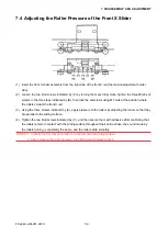
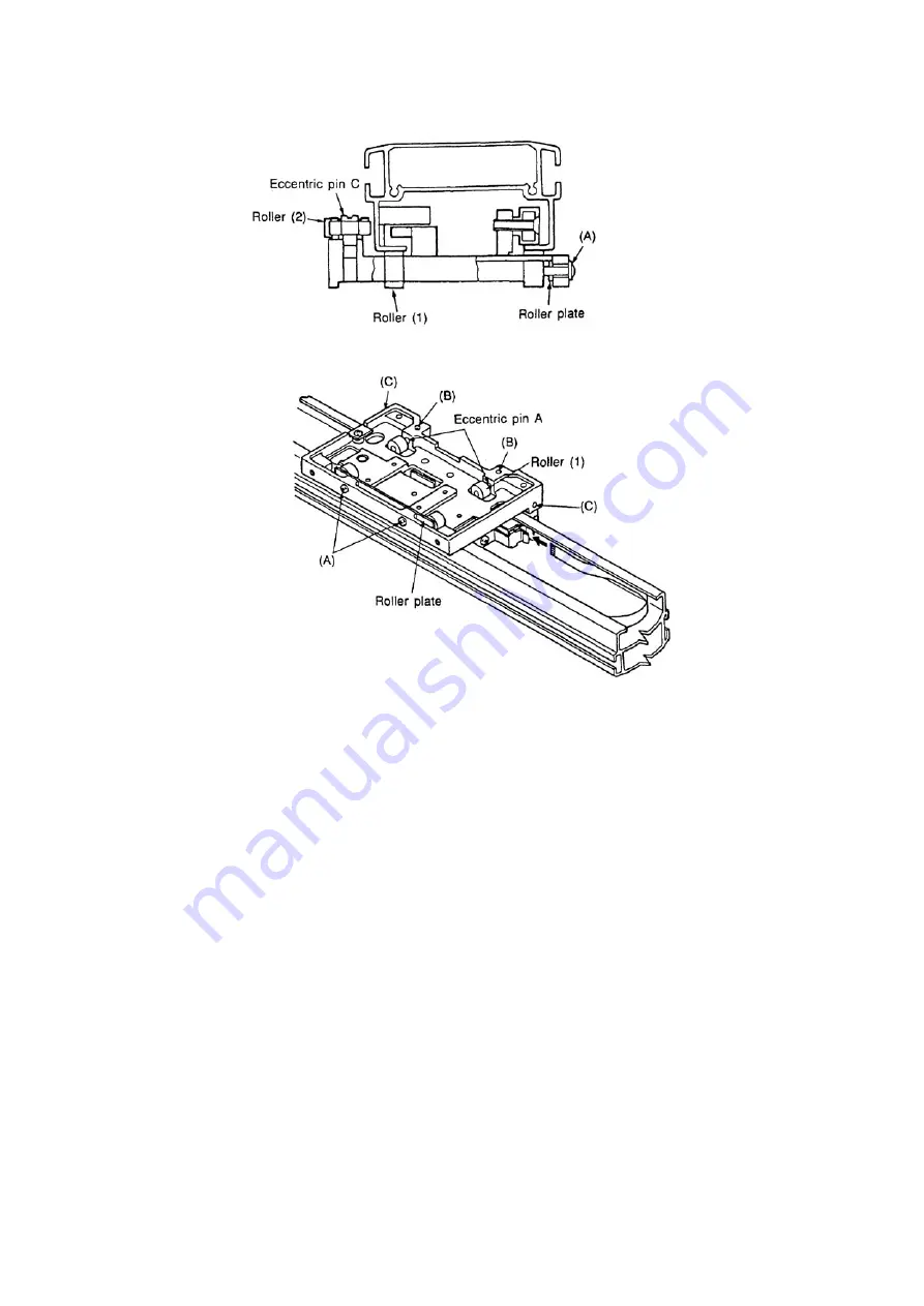
7.6 Adjusting the Roller Pressure of the Y Slider
(1) Mounting the Y slider onto the Y bar
• Loosen the two screws (A), lower the roller plate and temporarily secure it in that position.
• Loosen the setscrews (B) at the two eccentric pins A, then temporarily secure the roller (1) in a
lowered position.
• Loosen the set-screws (C) at the two eccentric pins C, then move roller (2) outside of the Y slider and
temporarily secure it in that position.
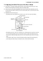
(2) Adjusting the Y slider’s roller pressure
• With the Y slider oriented as shown in the figure above, insert it onto the Y bar, then move each roller
back into contact with the sliding surface by performing the steps in (1) above in reverse sequence.
• Visually confirm that each roller rotates while maintaining contact with the sliding surface. Check that
there is no play in the front, back, or side directions.
• Make sure there are no discrepancies in the “grating” load of the rollers.
• The sliding load shall be 30 gf ± 5.
• After the adjustment is completed, apply adhesive to the four set-screws.
Summary of Contents for FC2240
Page 1: ...CUTTING MACHINE SERVICE MANUAL FC2240 FC2240 UM 251 04 9370...
Page 2: ......
Page 8: ...FC2240 UM 251 9370 vi...
Page 38: ...FC2240 UM 251 9730 3 15 3 OPERATIONS Sample printout by the CONDITION function...
Page 42: ...FC2240 UM 251 9730 4 2 4 DAILY MAINTENANCE AND STORAGE...
Page 70: ...FC2240 UM 251 9370 7 26 7 DISASSEMBLY AND ADJUSTMENT...

