FC2240-UM-251-9370
7-25
7. DISASSEMBLY AND ADJUSTMENT
7.13.3 Attaching the Electrostatic Adhesion Plate
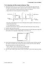
(1) Temporarily fasten the side cover, line up the holes for the high-voltage power supply cable on the
writing panel and the electrostatic adhesion plate and position according to the following conditions.
• Use the origin side (front X rail side and left side cover side) as the reference.
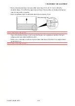
• Position about 2 mm from the origin side as in the figure below.
• Since there are slight differences in the size of electrostatic adhesion plates, the dimensions are not
specified with great precision.
• “A” in the diagram above is not 2 mm.
• Be careful not to let any dirt or dust get under the electrostatic adhesion plate during positioning.
(2) Secure the origin side with strong tape.
(3) Peel off and fold back the backing sheet of the double-sided tape at the high-voltage power supply cable
side for about 100 mm and paste on without letting in any dirt, dust, or air.
(4) Peel off the strong tape used for securing in Step (1) above, and while one person holds the origin side
and checks for and points out any unevenness, the other two persons peel off the double-sided tape
backing sheet and paste on by sliding their hands along.
• If dust or dirt gets in, remove it with tweezers or your fingernail tips.
• If air gets in, drive out the air at 5 mm intervals by kneading softly.
(5) When the entire surface has been spread out, attach it by sliding your hand across it again and pressing
it.
Summary of Contents for FC2240
Page 1: ...CUTTING MACHINE SERVICE MANUAL FC2240 FC2240 UM 251 04 9370...
Page 2: ......
Page 8: ...FC2240 UM 251 9370 vi...
Page 38: ...FC2240 UM 251 9730 3 15 3 OPERATIONS Sample printout by the CONDITION function...
Page 42: ...FC2240 UM 251 9730 4 2 4 DAILY MAINTENANCE AND STORAGE...
Page 70: ...FC2240 UM 251 9370 7 26 7 DISASSEMBLY AND ADJUSTMENT...

