FC2240-UM-251-9370
8-18
8. ELECTRICAL ADJUSTMENTS
8.13 Adjusting the Pen Interval
This enables adjustment of the distance between the origins for Pen 1 and Pen 2.
Note: Pens are used to draw lines for this adjustment. As described below, mount pens in the Pen 1 and Pen
2 positions, then specify their conditions.
Procedure
(1) Press the PAUSE key to select PAUSE mode.
(2) Press the NEXT key.
The LCD panel displays the screen below.
PEN ADJ. PEN U/D
BUFFER CLR. VIEW
(3) Press the [F1] key (PEN ADJ.) to display the menu below.
INTERVAL ADJUST
X= 0 Y= 0
(4) Mount pens in the Pen 1 and Pen 2 positions.
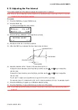
(5) When the TEST key is pressed, the lines shown below are drawn.
(6) Adjust the deviation of Pen 1 based on the lines drawn by Pen 2.
To adjust the X-axis deviation, press the [F2] key and then use the
and
keys to adjust the
numeric value.
To adjust the Y-axis deviation, press the [F4] key and then use the
and
keys to adjust the
numeric value.
The X= and Y= values can be specified in a range of -80 to +80 in 1-unit steps.,
The numeric value of 1 corresponds to 0.05 mm. To correct a deviation of 0.3 mm, for example, input 6.
(7) Press the ENTER key to register your INTERVAL ADJUST setting.
(8) Press the PAUSE key to cancel PAUSE mode, and the turn off the plotter.
Note: Your INTERVAL ADJUST setting is retained in the plotter’s internal memory even while the plotter is
turned off.
Summary of Contents for FC2240
Page 1: ...CUTTING MACHINE SERVICE MANUAL FC2240 FC2240 UM 251 04 9370...
Page 2: ......
Page 8: ...FC2240 UM 251 9370 vi...
Page 38: ...FC2240 UM 251 9730 3 15 3 OPERATIONS Sample printout by the CONDITION function...
Page 42: ...FC2240 UM 251 9730 4 2 4 DAILY MAINTENANCE AND STORAGE...
Page 70: ...FC2240 UM 251 9370 7 26 7 DISASSEMBLY AND ADJUSTMENT...

