FC7000-UM-251-9370
3-7
3. OPERATIONS
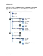
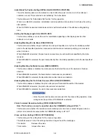
• Enabling or Disabling the 1/2 Pen Setting (CHECK PEN)
Note: This function can only be specified for a 2-pen model.
This function checks whether the physical PEN 2 is actually mounted in the pen station during the media
detection operation on a 2-pen model.
When ENABLED is selected, a check is performed
When DISABLED is selected, a check is not performed. If DISABLED is selected, always check that
PEN 2 is mounted in the pen station before turning on the power.
• Fan Suction Setting (FAN POWER)
This function sets the suction force used to affix media to the plotter.
Thin media:
Weak
Normal media:
Normal
• Enabling/Disabling the Beep Setting (BEEP FOR KEY OPERATION)
This function selects whether to enable or disable the beep that is emitted whenever a control panel key
is pressed.
ON:
The beep sounds.
OFF:
The beep does not sound.
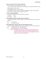
• Enabling/Disabling Auto Registration Mark Recognition (MARK AUTO SCAN)
This function enables or disables the automatic sensing of registration marks from the plug-in software.
ON:
The registration marks are sensed automatically.
OFF:
The registration marks are not sensed automatically.
CAUTION: If DISABLED was selected for the media or pinch roller sensors, be sure
to specify the cutting or plotting area. If the cutting or plotting area is not
specified, the blade tip and the cutting mat may be damaged, and the pen
carriage may strike the sides of the plotter.
Summary of Contents for FC7000-100
Page 2: ......
Page 8: ......
Page 34: ......
Page 38: ......
Page 100: ......
Page 110: ......
Page 112: ...FC7000 UM 251 9370 10 2 10 PARTS LIST 1 2 3 4 5 6 7 8 10 9 Control Panel Assy 11 12...
Page 114: ...FC7000 UM 251 9370 10 4 10 PARTS LIST Control Panel 5 4 3 6 9 8 7 1 1 2 3 5 10...
Page 126: ......
Page 141: ...FC7000 UM 251 9370 11 15 11 BLOCK DIAGRAMS AND CIRCUIT DIAGRAMS 11 3 2 Main Board CPU...
Page 142: ...FC7000 UM 251 9370 11 16 11 BLOCK DIAGRAMS AND CIRCUIT DIAGRAMS 11 3 3 Main Board FPGA...
Page 143: ...FC7000 UM 251 9370 11 17 11 BLOCK DIAGRAMS AND CIRCUIT DIAGRAMS 11 3 4 Main Board I F...
Page 144: ...FC7000 UM 251 9370 11 18 11 BLOCK DIAGRAMS AND CIRCUIT DIAGRAMS 11 3 5 Main Board Motor Drive...
Page 145: ...FC7000 UM 251 9370 11 19 11 BLOCK DIAGRAMS AND CIRCUIT DIAGRAMS 11 3 6 Main Board Memory...
Page 146: ...FC7000 UM 251 9370 11 20 11 BLOCK DIAGRAMS AND CIRCUIT DIAGRAMS 11 3 7 Main Board Power Supply...

