FC7000-UM-251-9370
IV
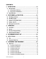
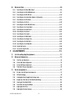
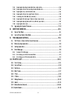
7.3.9 Adjusting the Auto-Registration Mark Sensor Sensitivity .......................................................... 7-20
7.3.10 Adjusting the Offset of the Auto-Registration Mark Sensor ...................................................... 7-21
7.3.11 Adjusting the Cross Cutter Home Position ............................................................................... 7-23
7.3.12 Adjusting the Offset of the Light Pointer Position ..................................................................... 7-25
7.3.13 Confirming the 2-Pen Model (2-pen model) ............................................................................. 7-26
7.3.14 Adjusting the Pen Exchange Y Direction Value (2-pen model) .................................................. 7-27
7.3.15 Adjusting the Spacing Between Pen 1 and Pen 2 (2-pen model) ............................................................7-29
7.3.16 Adjusting the Servo Gain ........................................................................................................ 7-31
7.4 Upgrading the System Firmware ..............................................................................7-32
8. SERVICE MODES ................................................................8-1
8.1 Sensor Test Mode ......................................................................................................8-1
8.2 Control Panel Switch Test Mode .................................................................................8-2
9. TROUBLESHOOTING .......................................................... 9-1
9.1 The Plotter is Turned On But Doesn’t Operate .............................................................9-1
9.2 Media Loading Operations .........................................................................................9-2
9.3 Cutting Operations ....................................................................................................9-3
9.4 Error Messages .........................................................................................................9-4
9.4.1 Hardware Error Messages ........................................................................................................9-4
9.4.2 Error Messages in GP-GL Command Mode ................................................................................9-5
9.4.3 Error Messages in HP-GL Emulation Mode ................................................................................9-6
10. PARTS LIST ......................................................................10-1
10.1 Outer Casing ...........................................................................................................10-1
10.2 Control Panel ..........................................................................................................10-3
10.3 Pen Block ................................................................................................................10-5
10.4 Main Frame .............................................................................................................10-7
10.5 Y Rail ......................................................................................................................10-9
10.6 Y Slider ................................................................................................................. 10-11
10.7 Wiring Harness ...................................................................................................... 10-12
10.8 Labels ................................................................................................................... 10-13
10.9 Media Stocker, Stand .................................................................... 10-14
10.10 Option Basket ........................................................................................................ 10-15
Summary of Contents for FC7000-100
Page 2: ......
Page 8: ......
Page 34: ......
Page 38: ......
Page 100: ......
Page 110: ......
Page 112: ...FC7000 UM 251 9370 10 2 10 PARTS LIST 1 2 3 4 5 6 7 8 10 9 Control Panel Assy 11 12...
Page 114: ...FC7000 UM 251 9370 10 4 10 PARTS LIST Control Panel 5 4 3 6 9 8 7 1 1 2 3 5 10...
Page 126: ......
Page 141: ...FC7000 UM 251 9370 11 15 11 BLOCK DIAGRAMS AND CIRCUIT DIAGRAMS 11 3 2 Main Board CPU...
Page 142: ...FC7000 UM 251 9370 11 16 11 BLOCK DIAGRAMS AND CIRCUIT DIAGRAMS 11 3 3 Main Board FPGA...
Page 143: ...FC7000 UM 251 9370 11 17 11 BLOCK DIAGRAMS AND CIRCUIT DIAGRAMS 11 3 4 Main Board I F...
Page 144: ...FC7000 UM 251 9370 11 18 11 BLOCK DIAGRAMS AND CIRCUIT DIAGRAMS 11 3 5 Main Board Motor Drive...
Page 145: ...FC7000 UM 251 9370 11 19 11 BLOCK DIAGRAMS AND CIRCUIT DIAGRAMS 11 3 6 Main Board Memory...
Page 146: ...FC7000 UM 251 9370 11 20 11 BLOCK DIAGRAMS AND CIRCUIT DIAGRAMS 11 3 7 Main Board Power Supply...


