FC7000-UM-251-9370
7-5
7. ADJUSTMENT
7.2.4 Pinch Roller Pressure Adjustment
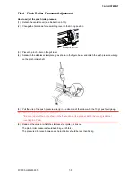
How to adjust the pinch roller pressure
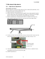
(1) Detach the center cover (see Subsection 6.1.3).
(2) Change the hold-down force switching lever to the Strong position.
Strong
hold-down force
Weak
hold-down force
(3) Place the pinch roller on the grit roller.
(4) Sandwich the stainless steel plate jig as shown in the figure below and catch the push pressure wire jig
on the pinch roller shaft.
(5) Pull the wire of the push pressure wire jig in the direction of the arrow with the 10 kgf push-pull gauge.
Note *Be sure to pull in the correct direction.
*Be sure to pull at the angle shown in the figure above (the angle at which the wire jig is almost
touching the Y rail).
(6) Read out the value at which the stainless steel plate jig slips out.
The pinch roller pressure should be 6.5 kg ±0.25 force.
The pressure difference between each pinch roller should be less than 0.4 kg.
Summary of Contents for FC7000-100
Page 2: ......
Page 8: ......
Page 34: ......
Page 38: ......
Page 100: ......
Page 110: ......
Page 112: ...FC7000 UM 251 9370 10 2 10 PARTS LIST 1 2 3 4 5 6 7 8 10 9 Control Panel Assy 11 12...
Page 114: ...FC7000 UM 251 9370 10 4 10 PARTS LIST Control Panel 5 4 3 6 9 8 7 1 1 2 3 5 10...
Page 126: ......
Page 141: ...FC7000 UM 251 9370 11 15 11 BLOCK DIAGRAMS AND CIRCUIT DIAGRAMS 11 3 2 Main Board CPU...
Page 142: ...FC7000 UM 251 9370 11 16 11 BLOCK DIAGRAMS AND CIRCUIT DIAGRAMS 11 3 3 Main Board FPGA...
Page 143: ...FC7000 UM 251 9370 11 17 11 BLOCK DIAGRAMS AND CIRCUIT DIAGRAMS 11 3 4 Main Board I F...
Page 144: ...FC7000 UM 251 9370 11 18 11 BLOCK DIAGRAMS AND CIRCUIT DIAGRAMS 11 3 5 Main Board Motor Drive...
Page 145: ...FC7000 UM 251 9370 11 19 11 BLOCK DIAGRAMS AND CIRCUIT DIAGRAMS 11 3 6 Main Board Memory...
Page 146: ...FC7000 UM 251 9370 11 20 11 BLOCK DIAGRAMS AND CIRCUIT DIAGRAMS 11 3 7 Main Board Power Supply...

