


FC8600-UM-251-9370 8-7
8 TROUBLESHOOTING
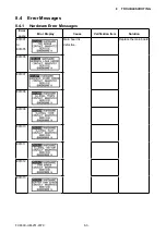
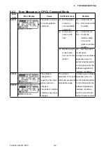
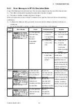
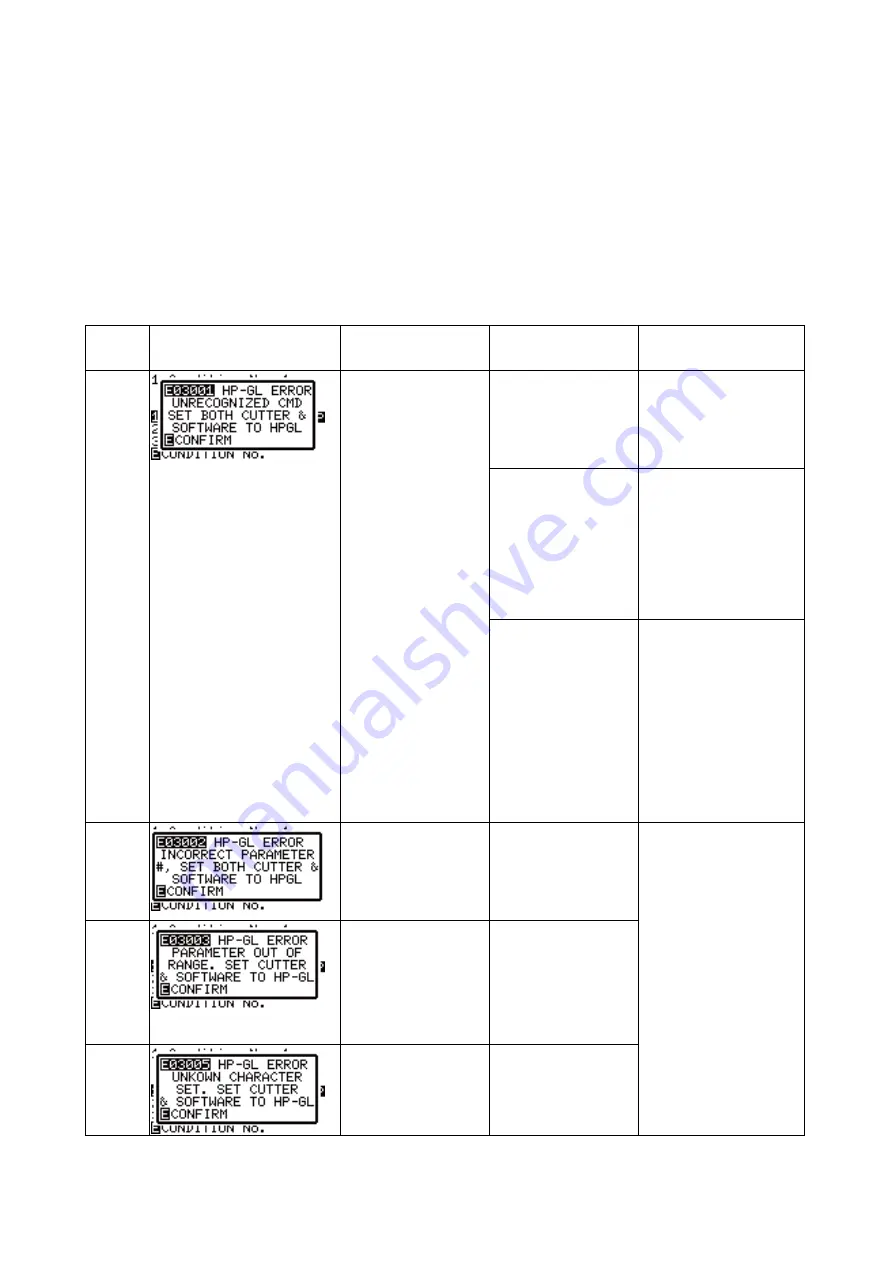
8.4.3 Error Messages in HP-GL Emulation Mode
If any of the following command errors occur, they are nearly always caused by one of the reasons below:
(1)
The software configuration regarding the output device has been changed.
(2) The plotter’s interface conditions have been changed.
When a command error occurs in HP-GL
TM
emulation mode, therefore, first check the two corresponding
points below:
(1)
Configure the software to drive your plotter, and ensure that the software’s interface conditions are
correctly set.
(2) Ensure that the plotter’s interface conditions are set to match those of the software.
Error
code
Error Display
Cause
Verification item
Solution
E03001
An unrecognizable
instruction was
executed.
Execute a
recognizable
command.
(1) Did the plotter
receive an
unrecognizable
command?
No .....Verify item (2)
Yes ....Send correct data
to plotter.
(2) Is there any
noise on the
line?
No .....Verify item (3)
Yes ....Check the
interface cable
or move the
plotter to another
location.
(3) Has the correct
model name
been set for the
plotter?
No .....Set the correct
model name.
Configure your software
application menu to
permit Graphtec plotter
control. Re-specify the
software application’s
interface conditions.
E03002
A command was
executed with the
wrong number of
parameters.
Execute the
command with the
correct number of
parameters.
Configure your software
application menu to
permit Graphtec plotter
control. Re-specify the
software application’s
interface conditions.
Set the correct model
name if it was incorrect.
E03003
A command
containing an
unusable parameter
was specified.
Execute the
command with
its parameters
specified within their
permissible ranges.
E03005
An unrecognizable
character set was
specified.
Specify a
recognizable
character set.
Summary of Contents for FC8600-100
Page 1: ...CUTTING PLOTTER SERVICE MANUAL FC8600 60 75 100 130 160 FC8600 UM 251 07 9370 ...
Page 2: ......
Page 4: ...FC8600 UM 251 9370 II ...
Page 32: ......
Page 103: ...FC8600 UM 251 9370 7 43 7 ADJUSTMENT ...
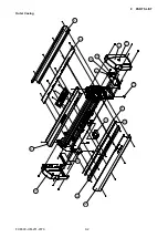
Page 124: ...FC8600 UM 251 9370 9 2 9 PARTS LIST Outer Casing 4 6 2 3 9 13 11 12 14 15 10 1 16 8 7 5 ...
Page 141: ...FC8600 UM 251 9370 10 3 10 BLOCK DIAGRAMS AND CIRCUIT DIAGRAMS 10 2 2 Main Board CONNECTOR ...
Page 142: ...FC8600 UM 251 9370 10 4 10 BLOCK DIAGRAMS AND CIRCUIT DIAGRAMS 10 2 3 Main Board MOTOR DRIVER ...
Page 143: ...FC8600 UM 251 9370 10 5 10 BLOCK DIAGRAMS AND CIRCUIT DIAGRAMS 10 2 4 Main Board FPGA ...
Page 144: ...FC8600 UM 251 9370 10 6 10 BLOCK DIAGRAMS AND CIRCUIT DIAGRAMS 10 2 5 Main Board I F ...
Page 145: ...FC8600 UM 251 9370 10 7 10 BLOCK DIAGRAMS AND CIRCUIT DIAGRAMS 10 2 6 Main Board MEMORY ...
Page 147: ...FC8600 UM 251 9370 10 9 10 BLOCK DIAGRAMS AND CIRCUIT DIAGRAMS 10 2 8 LAN Board ...
Page 148: ...FC8600 UM 251 9370 10 10 10 BLOCK DIAGRAMS AND CIRCUIT DIAGRAMS 10 2 9 Light Pointer ...
Page 149: ...FC8600 UM 251 9370 10 11 10 BLOCK DIAGRAMS AND CIRCUIT DIAGRAMS 10 2 10Pen Relay Board ...
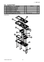
Page 151: ...FC8600 UM 251 9370 10 13 10 BLOCK DIAGRAMS AND CIRCUIT DIAGRAMS 10 2 13Control Panel Board ...
Page 152: ...FC8600 UM 251 9370 10 14 10 BLOCK DIAGRAMS AND CIRCUIT DIAGRAMS 10 2 14Cam Sensor Board ...