FC9000-UM-251-9370 8-23
8 Electrical Adjustment
8.12 Adjusting the friction
This adjustment will set the friction coefficient for the X and Y motors.
Perform this procedure if adjustment values could not copy from the SUB-NVRAM when replacing the main
board.
When the X or Y motor was replaced, perform this adjustment.
Required jigs
•
Prepare the following size of Cutting film.
FC9000-75 and 100: (Length) 1200 mm x (Width) 762 mm (30 inch)
FC9000-140 and 160: (Length) 1200 mm x (Width) 1372 mm (54 inch)
If you don't have above width of cutting film, prepare at least 30 inch wider cutting film.
And the loadable widest cutting film is better for this adjustment.
Preparation
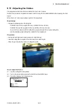
• Set the left and right push rollers pressure to high (Strong).
•
Load the cutting film as length of front and rear to be same length.
•
Move the pen block to the center of cutting film width.
How to adjust the friction
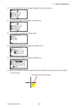
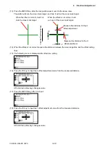
(1)
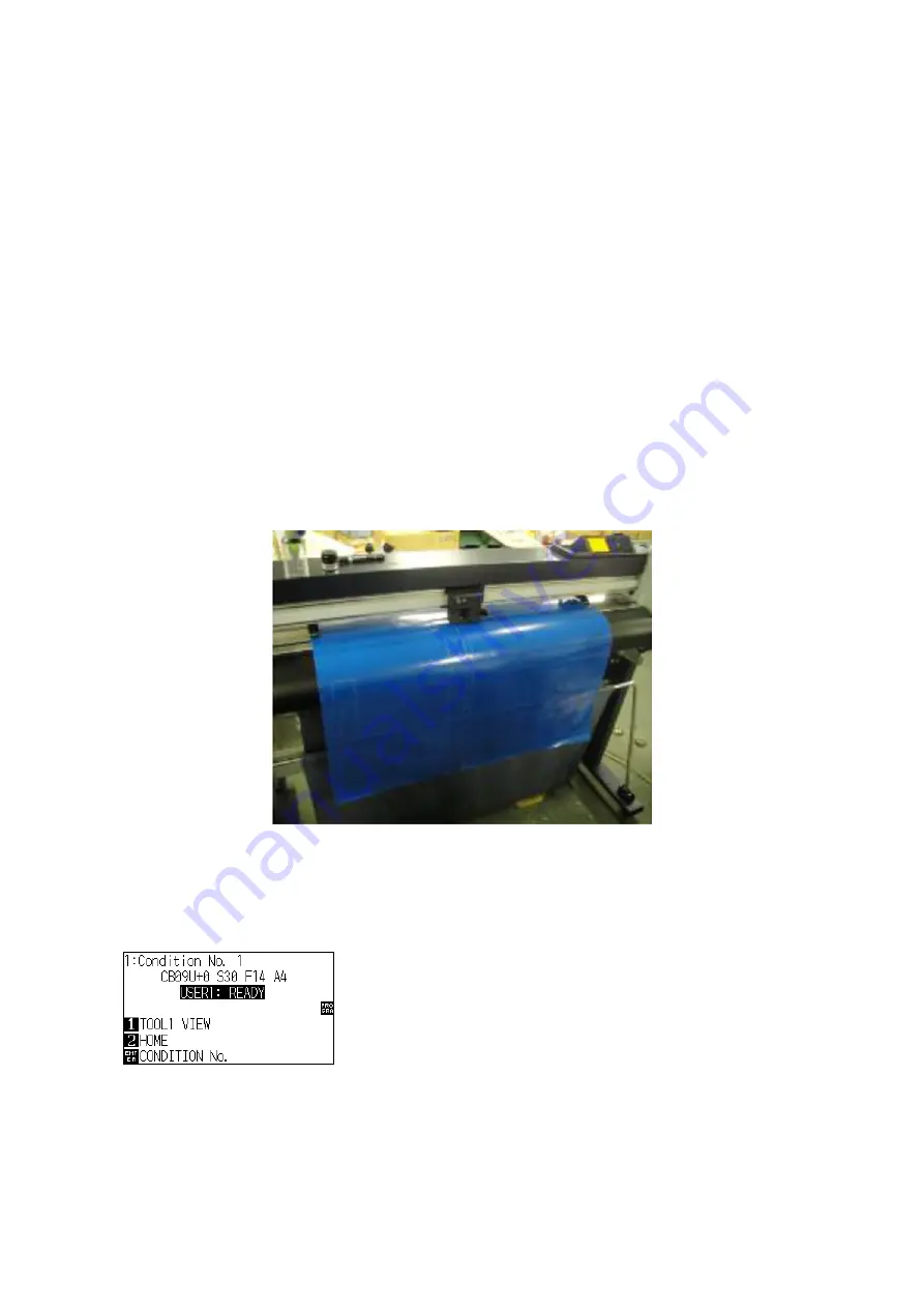
Load the cutting film to the plotter.
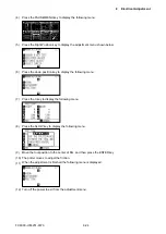
(2) Turn on the power while pressing the SLOW and the ENTER keys.
(3) The plotter displays the following menu.
Summary of Contents for FC9000-100
Page 1: ...CUTTING PLOTTER SERVICE MANUAL FC9000 75 100 140 160 FC9000 UM 251 01 9370...
Page 2: ......
Page 4: ...FC9000 UM 251 9370 II...
Page 38: ......
Page 201: ...FC9000 UM 251 9370 10 2 10 PARTS LIST Outer Casing 1 2 3 4 10 7 11 5 16 15 6 12 12 9 13 14 8...

