FC9000-UM-251-9370 2-2
2 Setup
2.2
Assembling the stand and basket to the Plotter
Procedure
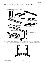
(1) Take out the following part of stand from the packing box.
The long parts are in the packing box of main unit.
Stand side bar x 2
Stock roller x 2
Media stocker roller L and R
Allen wrench (for M5 cap screw
M5L16 Cap screw x 16
M5L10 Cap screw x 16
Basket Cloth Arm x 4
Basket tube short x 2
Basket tube long x 1
Basket tube hanger bracket x 2
Basket Cloth x 1
Stopper x 2
Center bar x 1
Foot x 2
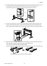
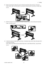
(2) Assemble the left and right stand sides. Insert the four M5L16 cap screws (long) to the thread of the
stand side bar by hand, and then tighten them by hand. Then fasten four M5L16 cap screws by using
the Allen wrench.
Summary of Contents for FC9000-100
Page 1: ...CUTTING PLOTTER SERVICE MANUAL FC9000 75 100 140 160 FC9000 UM 251 01 9370...
Page 2: ......
Page 4: ...FC9000 UM 251 9370 II...
Page 38: ......
Page 201: ...FC9000 UM 251 9370 10 2 10 PARTS LIST Outer Casing 1 2 3 4 10 7 11 5 16 15 6 12 12 9 13 14 8...


