FC9000-UM-251-9370 2-3
2 Setup
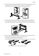
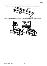
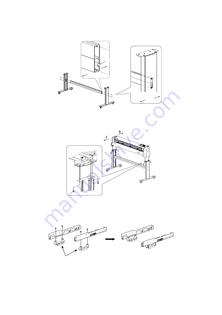
(3) Insert the four M5L16 cap screws (long) to the thread of the center bar by hand (two on each side), and
then tighten them by hand. Then fasten four M5L16 cap screws by using the Allen wrench.
There is front and rear for the center bar, when instal the plotter onto stand, confirm it.
Front
Rear
Front
Rear
Confirm this groove.
(4) Confirm the front side and the rear side for the stand by shape of center bar. Mount the plotter on the
stand by inserting the positioning pins on the stand into the positioning holes on the underside of the
plotter. Fasten with the four M5L10 cap screws (two short screws for each side), using the Allen wrench.
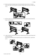
(5) Attach the basket tube hanger brackets to each of the media stocker roll brackets. Fasten with the four
M5L10 cap screws (two short screws for each side), using the Allen wrench.
There is direction to attach the basket tube hanger brackets.
Attach the basket tube hanger brackets to the media stocker roll brackets as shown in the picture below.
Right
Right
Left
Left
When attaching the bracket, confirm the direction of bracket.
Summary of Contents for FC9000-100
Page 1: ...CUTTING PLOTTER SERVICE MANUAL FC9000 75 100 140 160 FC9000 UM 251 01 9370...
Page 2: ......
Page 4: ...FC9000 UM 251 9370 II...
Page 38: ......
Page 201: ...FC9000 UM 251 9370 10 2 10 PARTS LIST Outer Casing 1 2 3 4 10 7 11 5 16 15 6 12 12 9 13 14 8...


