FC9000-UM-251-9370 12-5
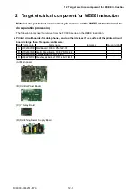
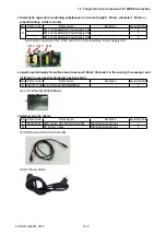
12 Target electrical component for WEEE instruction
• Removing (B) Control Panel Board, (E) LCD
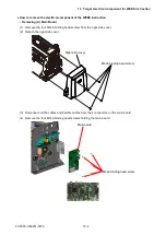
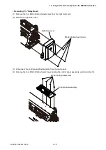
(1) Remove the four M4L6 binding head screws from the right side cover.
(2) Detach the right side cover.
M4L6 binding head screw
Right side cover
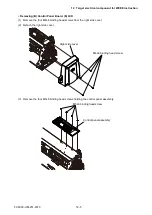
(3) Remove the four M3L6 binding head screws holding the control panel assembly.
M3L6 binding head screw
Control panel assembly
Summary of Contents for FC9000-100
Page 1: ...CUTTING PLOTTER SERVICE MANUAL FC9000 75 100 140 160 FC9000 UM 251 01 9370...
Page 2: ......
Page 4: ...FC9000 UM 251 9370 II...
Page 38: ......
Page 201: ...FC9000 UM 251 9370 10 2 10 PARTS LIST Outer Casing 1 2 3 4 10 7 11 5 16 15 6 12 12 9 13 14 8...

