FC9000-UM-251-9370 4-1
4 OPERATIONS
4 OPERATIONS
4.1 Control Panel
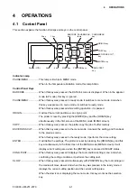
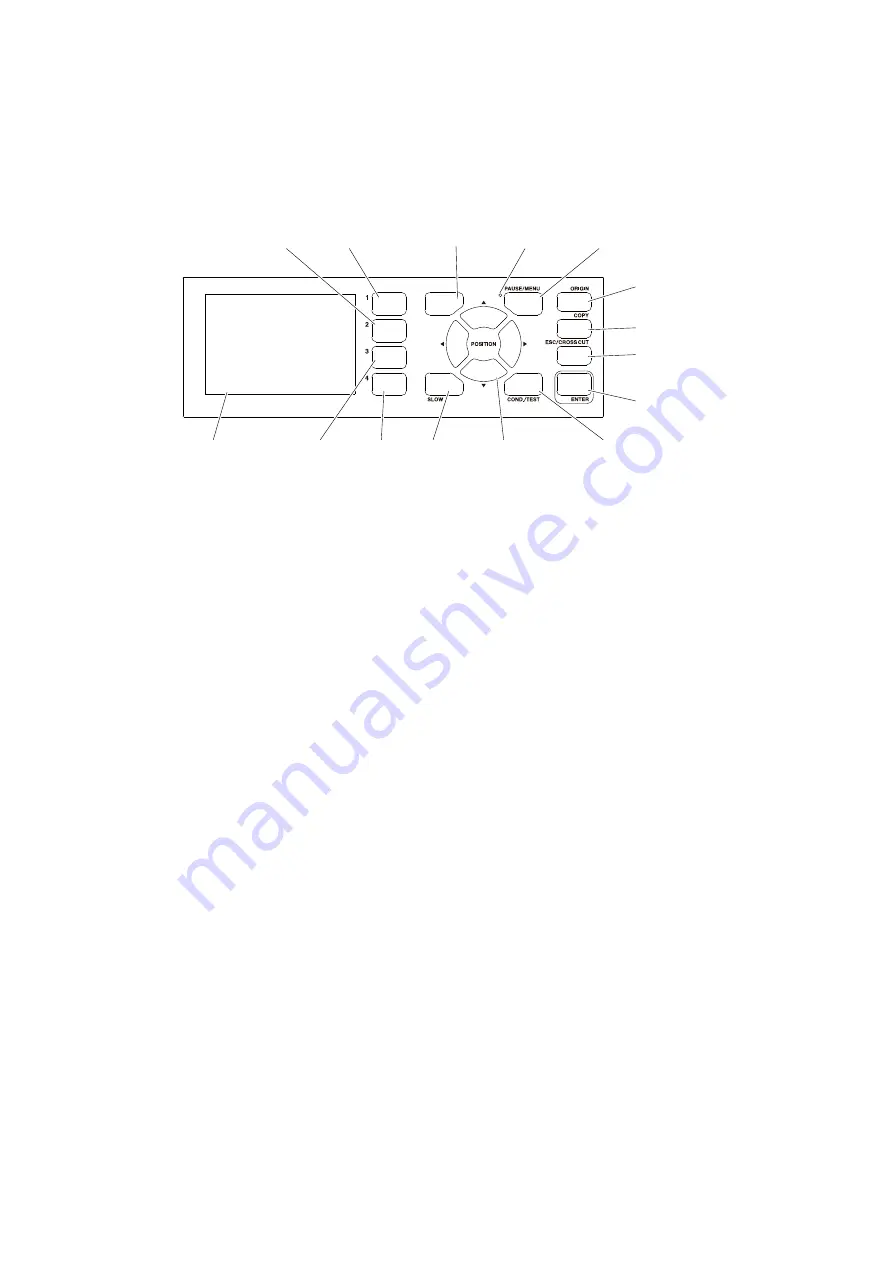
This section explains the function of lamps and keys on the control panel.
BARCODE
key
BARCODE
1 key
2 key
ESC/CROSS CUT
key
PAUSE/MENU
lamp
PAUSE/MENU
key
ORIGIN key
ENTER key
COND./TEST
key
POSITION keys
SlOW key
3 key
4 key
COPY key
Screen (LCD)
Indicator Lamp
PAUSE/MENU ................ This lamp is lit while in MENU mode.
When in the Temperature limitation mode, this lamp blinks.
Control Panel Keys
BARCODE ...................... When this key was pressed, the DATA link menu is displayed. When in the apparel
mode (AP mode), this key is ignored.
PAUSE/MENU ................ When this key was pressed in ready mode, it switches to menu mode. And when
this key was pressed in menu mode, it switches to ready mode.
When this key was pressed while cutting operation, it is paused.
ORIGIN ........................... It will set the current position as an origin point.
The plotter is reset by pressing the [ENTER] key and the [ORIGIN] key
simultaneously in the first screen of the MENU mode (MENU screen).
COPY ............................. When this key was pressed, the plotter copy the job of buffer memory.
ESC/CROSS CUT .......... When this key was pressed in the menu mode, it cancels the setting, and then back
to the previous menu.
When this key was pressed in the ready mode, it performs the cross cutting.
ENTER ........................... It will define the settings. The plotter is reset by pressing the [ORIGIN] key and this
key simultaneously in the first screen of the MENU mode (MENU screen). It will
display current cutting area when the [ENTER] key is pressed in READY status.
COND./TEST .................. When this key was pressed it displays the tool condition setting menu. And when
confirming the cutting conditions, it performs the cutting test.
SLOW ............................. When this key was pressed simultaneously with POSITION key, the tool carriage or
the media will move slower. And when this key was pressed in the ready mode, it
displays the current cutting position and the current cutting area.
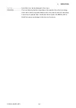
When the slow icon is displaying the menu mode, this key works as the selection
key.
Summary of Contents for FC9000-100
Page 1: ...CUTTING PLOTTER SERVICE MANUAL FC9000 75 100 140 160 FC9000 UM 251 01 9370...
Page 2: ......
Page 4: ...FC9000 UM 251 9370 II...
Page 38: ......
Page 201: ...FC9000 UM 251 9370 10 2 10 PARTS LIST Outer Casing 1 2 3 4 10 7 11 5 16 15 6 12 12 9 13 14 8...

