FC9000-UM-251-9370 7-20
7 DISASSEMBLY AND REASSEMBLY
7.2.7 Replacing the Y-belt
How to detach the Y-belt
(1) Detach the right side cover (Refer to subsection 7.1.1.).
(2) Detach the left side cover (Refer to subsection 7.1.2.).
(3) Detach the control panel assembly (Refer to subsection 7.1.3.).
(4) Detach the center cover (Refer to subsection 7.1.4.).
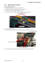
(5) Detach the pen block (Refer to subsection 7.2.6.).
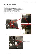
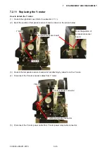
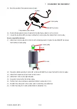
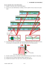
(6) Mark the position of Y idler pulley shaft as shown in picture below.
Y idler pulley Shaft
Y idler pulley
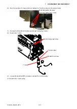
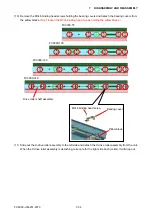
(7) Loosen the two M3L28 binding head screws adjusting the Y-belt tension.
M3L28 binding head screw
Summary of Contents for FC9000-100
Page 1: ...CUTTING PLOTTER SERVICE MANUAL FC9000 75 100 140 160 FC9000 UM 251 01 9370...
Page 2: ......
Page 4: ...FC9000 UM 251 9370 II...
Page 38: ......
Page 201: ...FC9000 UM 251 9370 10 2 10 PARTS LIST Outer Casing 1 2 3 4 10 7 11 5 16 15 6 12 12 9 13 14 8...

