FC9000-UM-251-9370 7-39
7 DISASSEMBLY AND REASSEMBLY
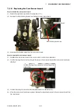
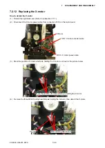
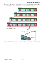
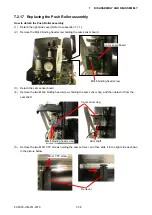
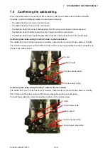
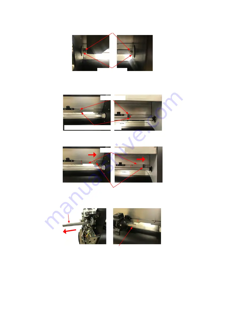
(6) Remove the two M3L10 binding head screws holding the right and the left cam shaft holder.
Cam shaft holder
M3L10 binding head screw
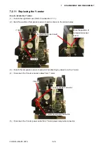
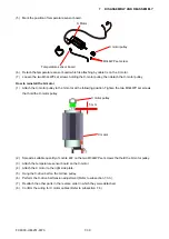
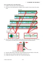
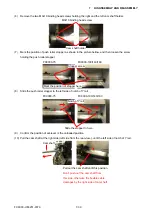
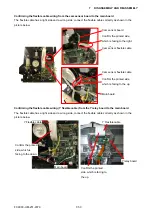
(7) Mark the position of push roller stopper as shown in the picture bellow, and then loosen the screw
holding the push roller stopper.
FC9000-75
FC9000-100/140/160
Mark the position of stopper here.
Stopper screw
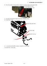
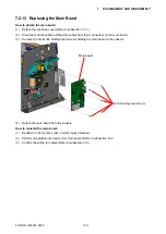
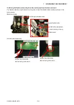
(8) Slide the push roller stopper to the left side of notch of Y rail.
FC9000-75
FC9000-100/140/160
Slide the stopper to here.
Notch of Y rail
(9)
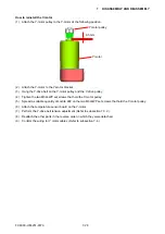
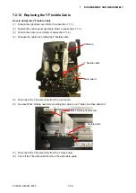
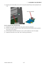
Confirm the position of set-lever is the unloaded position.
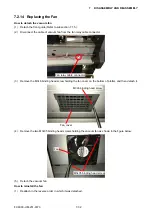
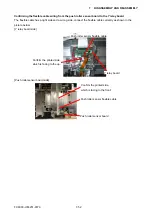
(10) Pull the cam shaft at the right side (left side from the rear view.), until the left side of notch of Y rail.
Cam shaft
Pull out the cam shaft until this position.
Don’t push out the cam shaft from
this side, otherwise the flexible cable
damages by the right side of cam shaft.
Summary of Contents for FC9000-100
Page 1: ...CUTTING PLOTTER SERVICE MANUAL FC9000 75 100 140 160 FC9000 UM 251 01 9370...
Page 2: ......
Page 4: ...FC9000 UM 251 9370 II...
Page 38: ......
Page 201: ...FC9000 UM 251 9370 10 2 10 PARTS LIST Outer Casing 1 2 3 4 10 7 11 5 16 15 6 12 12 9 13 14 8...

