FC9000-UM-251-9370 8-3
8 Electrical Adjustment
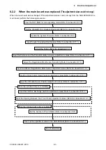
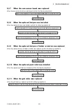
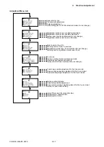
8.2.2 When the main board was replaced (The adjustment values could not copy.)
When the main board was exchanged, if the adjustment values could not copy from the SUB-NVRAM to the
main board, perform the following procedure.
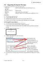
Update the System Firmware (Refer to subsection 8.6.).
Adjust the Registration Mark Sensor Sensitivity (Refer to subsection 8.14.).
Input the X Media Sensor Position adjustment values (Refer to subsection 8.17.1.).
Set the Number of Push Rollers (Refer to subsection 8.20.)
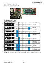
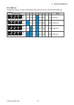
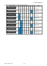
Set the dip switch for corresponding model (Refer to subsection 8.3.).
Input the pen force adjustment values (Refer to subsection 8.11.1.).
Adjust the friction (Refer to subsection 8.12.).
Input the Offset of Registration Mark Sensor adjustment value (Refer to subsection 8.15.1.).
Input the 2nd Pen Exchange position adjustment values (Refer to subsection 8.18.1.).
Input the Spacing Between Tool 1 and Tool 2 adjustment values (Refer to subsection 8.19.1.).
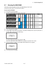
Clear the NOV-RAM for corresponding model (Refer to subsection 8.7.).
Input the Distance and the Perpendicularity Accuracy adjustment values (Refer to subsection 8.13.1.).
Input the Cross Cutter Home Position adjustment value (Refer to subsection 8.16.1.).
Back up the adjustment value to the SUB-NVRAM (Refer to subsection 8.21.).
End of adjustment
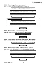
When the optional 2nd pen is installing:
When the optional push roller is installing:
Summary of Contents for FC9000-100
Page 1: ...CUTTING PLOTTER SERVICE MANUAL FC9000 75 100 140 160 FC9000 UM 251 01 9370...
Page 2: ......
Page 4: ...FC9000 UM 251 9370 II...
Page 38: ......
Page 201: ...FC9000 UM 251 9370 10 2 10 PARTS LIST Outer Casing 1 2 3 4 10 7 11 5 16 15 6 12 12 9 13 14 8...

